20
Installation Guide
20
tel - 1-800-477-2267
email - support@aampglobal.com
Illustrations are typical and may not match exact vehicle detail
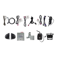
FCTP-MB1903
Sprinter Tow Package
Testing
Reconnect the three connectors to the dash panel that were removed on page 6, step 5.
Reconnect the negative battery cable.
Turn the ignition switch to ON, when the display of the unit comes on and is done with the boot up sequence,
test the system for functionality.
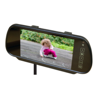
Activate the right turn signal. Verify the right camera is displaying on the radio’s screen.
Activate the left turn signal. Verify the left camera is displaying on the radio’s screen.
Place your foot on the brake and place the vehicle in reverse. The rear camera will display on the screen.
Place the vehicle back in park to go to back to the main display.
It is also possible to cycle through the inputs / cameras using the Keypad Tester included in the box. When
using the keypad tester, the camera label (left, right, front, rear) will be overlayed in the top left corner of the
screen to help identify which camera is being displayed. To use, press and release the button, the rst camera
in the rotation will be displayed. Press and release the button again to change to the next camera. Once the
camera rotation has nished, pressing the button again will exit camera mode and return back to the main
display
Once proper operation has been conrmed, ensure all factory components are in working order (radios touch
screen, radio controls, etc.) Once proper operation has been conrmed it is now time to reassemble the
vehicle.
Firmware Updates
Please visit www.EchoMaster.com and type “FCTP-MB1903” into the search bar. Once on the product page,
click on the downloads tab and download the application and rmware le needed to perform the update.
The FC-MBS module will need to be disconnected from the vehicle and placed into rmware update mode.
To do this nd the bank of 4 DipSwitches on the side of the module. Flip DipSwitch #4 to the ON position.
Once the application has been installed onto the computer. Connect the included USB port to the computer
and then to the module.
1
ON
2 3 4 5 6 7 8
FC-MBS
BLINDSPOT CAMERA INTERFACE
LVDS
CAMERA POWER
USB
1
ON
2 3 4 5 6
1
ON
2 3 4
USB DipSwitches