8
Installation Guide
8
tel - 1-800-477-2267
email - support@aampglobal.com
Illustrations are typical and may not match exact vehicle detail
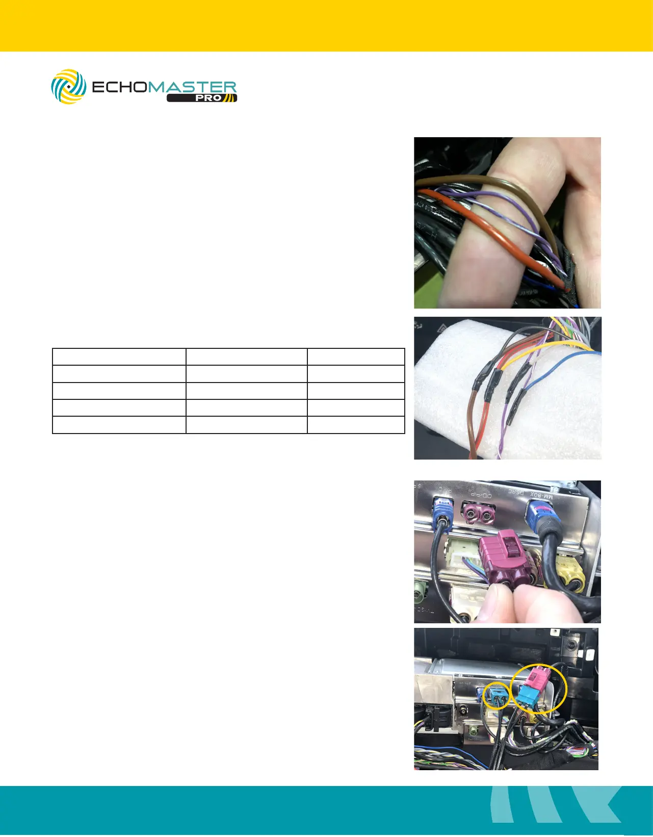
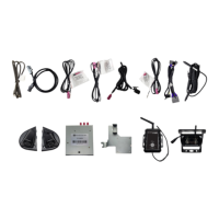
Step 1
Remove a small portion of the electrical tape banding the main
harness together to expose the power, ground and CANBus
connections.
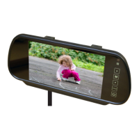
Interface Connections
Step 3
Disconnect the LVDS cable from the radio brain, labeled
“CID/PIP”, and connect the EchoMaster LVDS cable inline
with the factory cable and then back into the radio.
Step 2
Connect the wiring as follows:
Interface Wire Color Vehicle Wire Color Function
Yellow Red/Brown Constant +12v
Black Brown Ground
Blue Purple/White CAN +
Gray Purple CAN -
EchoMaster recommends soldering all connections.
FCTP-MB1903
Sprinter Tow Package