Do you have a question about the EchoMaster Pro FCTP-GM2003 and is the answer not in the manual?
Understanding Warning, Caution, and Note Symbols used in the manual.
Disclaimer regarding manufacturer responsibility for installation damage or misuse.
Precautions for disconnecting the battery and removing vehicle trim panels.
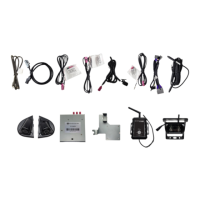
Identification and description of all parts included in the kit.
Details on dip switch settings and their corresponding functions for the module.
Instructions for removing the inner handle trim panel to access bolts.
Steps to locate and remove the 7mm bolts behind the door panel.
Procedure for releasing door trim clips and removing additional bolts.
Steps to detach the main door panel from the vehicle.
Final steps for lifting and removing the door panel after fasteners are released.
Instructions for disconnecting the door latch release cable and harness.
Procedure for removing the mirror cap screw and the mirror cap itself.
Instructions for disconnecting the temperature sensor connector.
Accessing the rubber membrane and making a slit for cable passage.
Feeding fish tape through the prepared opening to route cables.
Securing the camera cable to fish tape and pulling it through the membrane.
Releasing the rubber grommet and routing the cable into the door.
Removing the speaker to facilitate camera cable routing within the door.
Making a slit in the grommet to allow the camera cable to pass through.
Connecting the camera extension cables to the main camera cable.
Securing the camera cables to the factory wiring harness using zip ties.
Removing the door sill plate and adjusting the door boot for cable routing.
Removing the under dash beauty panel by releasing push pin fasteners.
Routing the fish tape along factory wiring to the door connector area.
Finalizing cable routing through the door boot and securing to factory wiring.
Instructions for routing the cable on the driver's side, avoiding moving parts.
Connecting the temperature sensor and camera pigtail to the camera pod.
Securing the camera pods into place and removing the protective lens film.
Preparing the surface and mounting the wireless camera receiver to the back window.
Routing the pigtail cable from the wireless receiver behind trim panels.
Connecting the receiver's cable to the in-line power filter cable.
Removing the rear door sill plate and tucking the cable under carpet.
Routing the cable from the rear sill to the front kick area under trim panels.
Reference to page 4 for setting DIP switches prior to module connection.
Connecting the power, camera, and LVDS harnesses to the GMS3 module.
Removing the 10mm retaining nut from the plastic bracket in the kick area.
Placing and securing the GMS3 mounting bracket onto the vehicle's factory bracket.
Identifying and disconnecting factory radio brain connectors and the LVDS cable.
Connecting the module's harnesses to the factory 28-pin connectors.
Connecting the LVDS connector and harnesses to the factory radio brain.
Ensuring module LEDs have stopped flashing before turning the ignition ON.
Navigating the warning screen and pressing OK to confirm usage terms.
Selecting and testing each camera view from the Intellihaul 2.0 home screen.
Adjusting the camera view by pressing and holding the screen center.
Verifying camera display with turn signals, reverse gear, and using the keypad tester.
This document is an installation guide for the EchoMaster FCTP-GM2003 Trailering Camera System, designed for Silverado/Sierra Heavy Duty Trucks (2020-Present) equipped with IOS and IOT Touchscreen Radios.
The EchoMaster FCTP-GM2003 Trailering Camera System enhances visibility for heavy-duty truck drivers, particularly when trailering. It integrates multiple cameras to provide comprehensive views around the vehicle, displayed on the factory touchscreen radio. The system includes left, right, front, and rear camera options, with provisions for additional trailer cameras. This allows drivers to monitor blind spots, assist with parking, and improve overall situational awareness, especially when maneuvering with a trailer. The system is designed to work seamlessly with the existing vehicle's infotainment system, offering an integrated user experience.
| Brand | EchoMaster Pro |
|---|---|
| Model | FCTP-GM2003 |
| Category | Automobile Accessories |
| Language | English |