12
b. From the Node’s DPX port, connect a coaxial connection to the
DPX receiver’s To Node DPX port.
c. Connect the Node to the DPX receiver and to the Home
Network. For additional information, see the
Product Launch Bulletin, Whole-Home HD DVR System.
Connect TV and receiver. Connect the receiver(s) to the TV(s) and power on the receiver(s)
and the TV(s). If a Receiver Setup Wizard displays, follow the on-screen prompts for this Wizard
to program the remote to the receiver, download software, and run Check Switch. Proceed to
step 8 after the Receiver Setup Wizard is complete.
Note:TheDownloadSoftwarestepoftheReceiverSetupWizardfailstoproceedifthereector
is not pointed correctly. If you see a pop-up instructing you to make sure that all cables leading to
thereceiverareconnectedsecurelyandcorrectly,verifyyourreectorispointedcorrectlybefore
selecting Continue on this screen.
If a Receiver Setup Wizard does not appear, display the Point Dish screen (if not shown, for most
receivers, press MENU-1-1 if in Factory software or MENU-6-1-1 if in Production software on
the remote control) and continue to step 10.
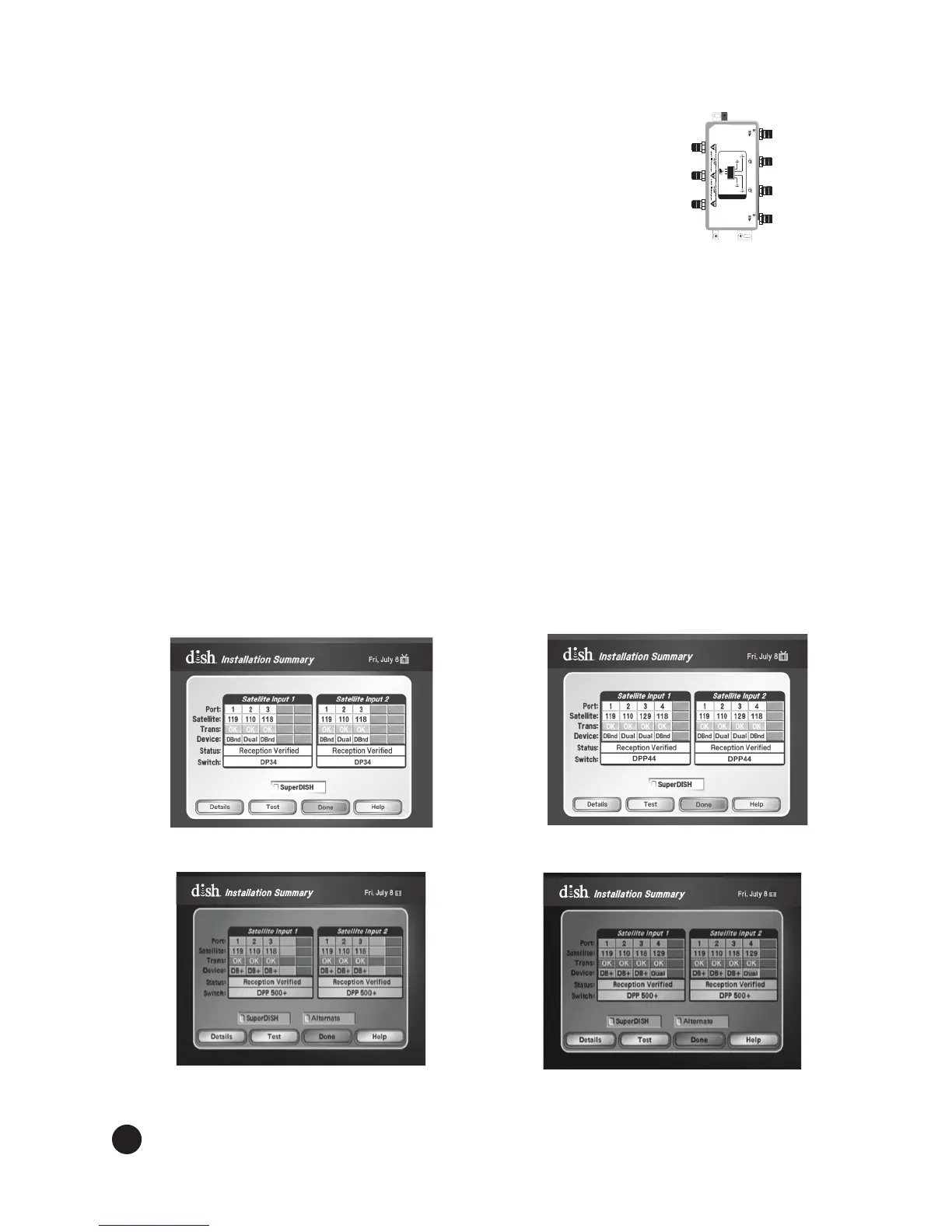
Follow instructions provided in the Installation Wizard or Run Check Switch. If
the Receiver Setup Wizard appears, follow the instructions provided and continue with step 13;
otherwise, from the Point Dish screen, run Check Switch. When the Check Switch procedure
nishes,youshouldseeanInstallation Summary screen similar to the ones shown in Figures
11, 12, 13, or 14. Make sure the summary screen shows reception from the 110°W, 118.7°W, and
119°W (and129°W for DISH 1000+) satellites on all available satellite tuners. The Installation
Summary screen only displays if you have run Check Switch.
9.
10.
MMTTVV-FMYYXXXXX
TO CLIENTT O CLIENT
EchoStar Technologies L.L.C.
Grounding wire size: Copper wire-8-14 AWG
Copper coated steel wire-17 AWG
T
O
L
N
B
F
S
DUO NODE
185836
TO HOST
10.5-28V
TO HOST
10.5-28V
To
LNBF
To Home
Network
To DPX
Receiver
To DPX
Receiver
Figure 11. DISH 500+
Installation Summary
Figure 12. DISH 1000+
Installation Summary
Figure 13. DISH 500+ with DPP
500+ LNBF Installation Summary
Figure 14. DISH 1000+ with DPP
1000+ LNBF Installation Summary