Do you have a question about the Eclipse 5600 and is the answer not in the manual?
Legal information regarding copyright and usage rights for the publication.
Manufacturer's policy on product changes and limitations of liability.
Details Eclipse's liability limits and warranty terms for the Veri-Flame system.
Identifies the intended readers of the manual, including installers and technicians.
Outlines the manual's content and emphasizes adherence to safety and instructions.
Explains the meaning of symbols used in the document, such as Danger, Warning, Caution, and Note.
Details the components and models of the Veri-Flame system, including No Purge, Purge, and Modulation types.
Introduces the section detailing Veri-Flame specifications and dimensions.
Lists key technical specifications like supply voltage, temperature ranges, and flame failure response times.
Provides physical dimensions of the Veri-Flame unit and its mounting bases.
Details the purpose of DIP switches for system configuration and timing functions.
Specifies the location of DIP switches on the Veri-Flame unit, referring to figures.
Describes how to access the DIP switches by separating the Veri-Flame unit from its back box.
Outlines the DIP switch settings for No Purge models, detailing specific functions like recycling and pilot selection.
Explains DIP switch settings for Modulation and Purge models, covering purge times and post purge selection.
Introduces the section describing the features of the Veri-Flame system.
Lists standard functional features of the Veri-Flame models.
Explains the function of interlocks and limit switches wired to terminal 7 for burner control.
Details the function of the combustion air switch input for airflow verification.
Describes interlocking with the main valve closed switch for valve operation verification.
Explains the low fire start feature for modulation models, checking the low fire position.
Details the high fire purge check for modulation models, verifying high fire position and main valve closure.
Explains the recycle mode for restarting the sequence after flame or air failure.
Describes how to enter and exit pilot test mode using the TEST/RESET button for sequence verification.
Explains pilot mode selection via DIP switch for interrupted or intermittent pilot.
Details the post purge feature for maintaining fan output after interlocks open.
Describes the sequence during trial for ignition, pilot flame, and main flame energization.
Explains system errors, lockout conditions, and their associated LED indicators and reset procedures.
Details the high to low fire purge modulation feature and selectable purge times.
Explains the optional feature that holds the sequence until air switch input is confirmed.
Describes the optional remote display unit, its features, and connection requirements.
Details the optional feature requiring a reset after power application or interruption.
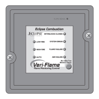
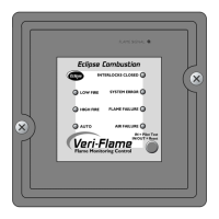
Describes the function of status lights (LEDs) and the TEST/RESET push-button on the Veri-Flame front cover.
Introduces the section on system installation procedures and diagrams.
Details wiring for interlocks and limit switches, ensuring proper burner control.
Explains wiring for the combustion air switch input for airflow verification and alternative connections.
Advises on routing ignition wiring to avoid electrical interference and ensure system stability.
Describes wiring for the low fire start switch for modulation models.
Details wiring for the main valve closed switch for valve operation verification.
Explains wiring for the high purge input for modulation models to check high fire position.
Describes the feature for remote mounting a switch to reset the Veri-Flame unit.
Details wiring and mounting for the remote display unit to minimize electrical interference.
| Brand | Eclipse |
|---|---|
| Model | 5600 |
| Category | Measuring Instruments |
| Language | English |