Do you have a question about the Eclipse RatioMatic 50 and is the answer not in the manual?
Specifies maximum allowable temperatures for cast head, alloy firing tube, and refractory block.
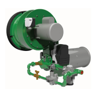
Refers to Figure 1 for detailed operating capacities and pressure specifications.
Defines the maximum process air velocity allowed past the burner.
Details requirements for blower motor, control motor, and ignition voltage.
Covers ambient temperature, weather protection, combustion air quality, and room opening requirements.
Warns against operating with insufficient gas inlet pressure, which can cause fuel-rich conditions and explosions.
Describes how the burner achieves turndown using two-position or modulating controls.
Details stroke, timing, and mounting for the control motor.
Explains the spark ignited pilot, pilot gas valve train, and pressure considerations.
Covers flame rod and UV scanner options for different burner sizes.
Specifies compliance with standards, check valves, and regulator requirements.
Emphasizes compliance with NFPA 86 and relevant local codes for safety equipment.
Instructs to keep the blower on until chamber temperature drops below 250°F to prevent damage.
Details on supporting the burner assembly, reinforcing the oven wall, and mounting orientation.
Ensures the blower motor is wired for correct rotation direction.
Notes on factory mounting or separate ordering for motors and kits.
Information on filter mounting and replacement, referencing Figure 6.
Covers factory mounting of switches or separate ordering with drawings.
Details remote mounting and connection to Tap 'D'.
Guidance on mounting, flow orientation, piping, and pressure loss considerations.
Recommends connecting the pilot gas valve train close to the pilot adjusting cock.
Instructions for mounting UV scanners and considerations for pipe nipples.
Advises against using pipe dope on spark plug threads.
Covers valve orientation, gas cock handles, and compliance with codes.
Specifies compliance with National Electric Code and authority jurisdiction.
Details factory settings, control panel, regulator adjustments, and initial checks for gas and air systems.
Lists parameters set at the factory: pilot input, air flow, and low fire gas flow.
Describes how to operate on pilot only and adjust pilot gas flow for reliable ignition.
Explains the need to cycle the control motor and how to manage temperature controls for adjustment.
Emphasizes adjusting main and pilot gas regulators to meet minimum pressures from Figure 1.
Instructs to close all manual and automatic gas valves before starting.
Details checking blower impeller rotation and ensuring correct airflow.
If applicable, start the fan to produce full process air flow past the burner.
Procedure to adjust the air butterfly valve to achieve minimum differential pressure at low fire.
Specifies the minimum required differential air pressure (0.2" w.c.) at low fire.
Procedure for setting the pilot gas flow to ensure reliable ignition and a steady flame signal.
Procedure for setting the high fire gas flow by measuring gas differential pressure.
Refers to Figure 1 for required gas differential pressure at high fire.
Procedure for setting the low fire flame quality and gas flow, potentially using the ratio regulator bias screw.
Cycle the burner to verify settings and record data. Proper shutdown procedure is crucial.
Lists common causes for pilot ignition failure, including air in the line and electrical issues.
Identifies causes like lean pilot, insufficient gas pressure, or marginal air pressure settings.
Attributes issues to insufficient gas flow or incorrect pilot gas cock adjustment.
Suggests checking for loose internals or contacting the factory for service.
Indicates gas flow is too high due to open butterfly valve or tight regulator spring.
Indicates gas flow is too low due to closed butterfly valve or loose regulator spring.
Points to too much gas flow or insufficient air flow due to filter/impeller issues.
Recommends a preventative maintenance schedule for reliability and productivity.
Verifies burner high and low fire air and gas settings.
Examines, cleans, or replaces air and gas filter elements.
Inspects all piping connections for leaks.
Tests flame supervision system functionality by simulating failures.
Verifies tightness of all bolts and screws.
Inspects the area around the burner mounting flange for signs of overheating.
Guidance on replacing the blower motor with a unit of matching nameplate ratings.
Refers to Figure 6 for instructions on replacing the filter element.
Details replacement procedures for ignition plugs and flame rods, noting common part numbers.