6
3.0 Installation
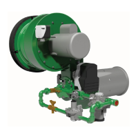
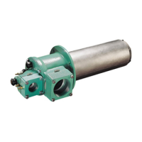
Burner Mounting See Figure 3 for installing a Ratiomatic with an alloy firing tube.
The flange will support only the weight of the burner assembly. Support burner
supply piping independently of the burner.
Reinforce the oven wall as required to support the burner’s weight.
Gas flow through the proportionator must be horizontal with the stem pointing up.
Blower Wiring Be sure the motor is wired to rotate in the proper direction.
Control Motors Factory mounted when ordered with the burner. Motors and mounting kits or-
dered separately include installation drawings.
Combustion Air Filters Factory mounted when ordered with the burner. Filters ordered separately include
installation drawings. See Figure 6 for filter element replacement.
Low/High Fire Limit Switches Factory mounted when ordered with the burner. Switches ordered separately in-
clude installation drawings.
Air Flow Switch Shipped loose for remote mounting. Connect with tubing to Tap “D,” Figure 4.
Main Gas Valve Trains Valve trains ordered from Eclipse are shipped loose for installation at the job site.
They must be mounted with horizontal flow and the actuators of the automatic
fuel shut-off valves pointing up.
Locate the main gas valve train as close as possible to the burner and connect it
with a straight run of pipe of the same pipe size as the valve train. If a reducing
nipple is necessary, install it at the inlet to the burner proportionator. Do not use
a reducing bushing in the proportionator inlet.
Be certain that piping losses between the valve train and burner are low enough
to provide the required gas supply pressures listed in Figure 1.
Pilot Valve Trains The pilot gas valve train should be connected as close as possible to the pilot
adjusting cock.
Flame Rod and U.V. Scanner See Figure 4. When mounting a UV scanner, use short pipe nipples to insure the
best possible field of view. A cooling air supply is not normally required.
Spark Plug Figure 4 shows the spark plug port. Do not use pipe dope on spark plug threads.
General Piping Suggestions Install all valves so that the arrow on the side of the valve body points in the di-
rection of flow. Install removable gas cock handles so that when the valve is in
the “off” position, the handle is 90° or at a right angle to the line of flow through
the valve.
Gas piping must comply with American National Standard “National Fuel Gas
Code”* (NFPA No. 54 or ANSI Z223.1), or must be acceptable to the authority
having jurisdiction.
General Wiring Suggestions Electrical wiring must comply with the National Electric Code*, (NFPA Std. 70 or
ANSI-CI 1981), or must be acceptable to the authority having jurisdiction.
*Available from:
National Fire Protection Association American National Standard Institute
Batterymarch Park 1430 Broadway
Quincy, Massachusetts 02269 New York, New York 10018
11
4.0 Start-Up And Adjustment (continued)
Step 4: Set High Fire Gas
With the pilot lit and the control motor in the low fire position, open the main gas
shut-off valve. The main flame should light.
Drive the control motor to its high fire position.
Measure the gas differential pressure as shown below.
High Fire Gas Differential Pressure See Figure 1.
If necessary, adjust the gas flow with the butterfly valve. The flame should be clear
blue as shown on the cover of this manual. If the flame is yellow, see Section 5.0,
“Troubleshooting.”
Tap “B”
Measure gas differential pressure
between this tap and a tap
in the chamber wall
Adjust Gas Here
50 through 600 Sizes 750 through 2500 Sizes