10
Eclipse RatioMatic Burners, RM Series, V5, Installation Guide 110, 12/3/2014
Supply Piping
Inlet pressure to the ratio regulator must stay within
specified limits. Refer to the appropriate RatioMatic
datasheet.
• Locate the valve train close to the burner. The gas
must reach the burner during the fixed trial for
ignition.
• Appropriately size shut off valves in the valve train.
• Make sure piping is large enough to accommodate
flow required to meet burner input.
• Minimize piping elbows.
• If a reducing nipple is necessary, install it at the inlet
to the burner proportionator. Do not use a reducing
bushing in the proportionator inlet.
Bypass Start Gas Piping (Optional for RM0050-
RM0700 Only)
Install the piping as shown in the schematics using the
following guidelines:
• Locate the bypass start gas solenoids close to the
burner. The gas must reach the burner during the
trial for ignition period.
• Minimize piping elbows.
• Install an adjustable limiting orifice (ALO) for start
gas adjustment. Refer to Bulletin 728 and 730 for
further information.
• Include a straight run of pipe at least 8" (192mm)
long before (upstream from) the start gas orifice
(optional) and at least 4" (96mm) long after
(downstream from) the start gas orifice.
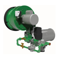
Figure 3.8. Bypass Start Gas Piping
■ Please verify that piping complies with all
applicable codes and/or standards.
Pilot Valve Trains (RM1000-RM3000)
The pilot gas valve train should be connected as close as
possible to the pilot adjusting cock.
Pipe Connections
• Installation of a pipe union in the gas line is
recommended to simplify burner removal.
• Use of flexible pipe is optional.
NOTE: Flexible pipe causes higher pressure drops than
standard pipe. Consider this when sizing your gas lines.
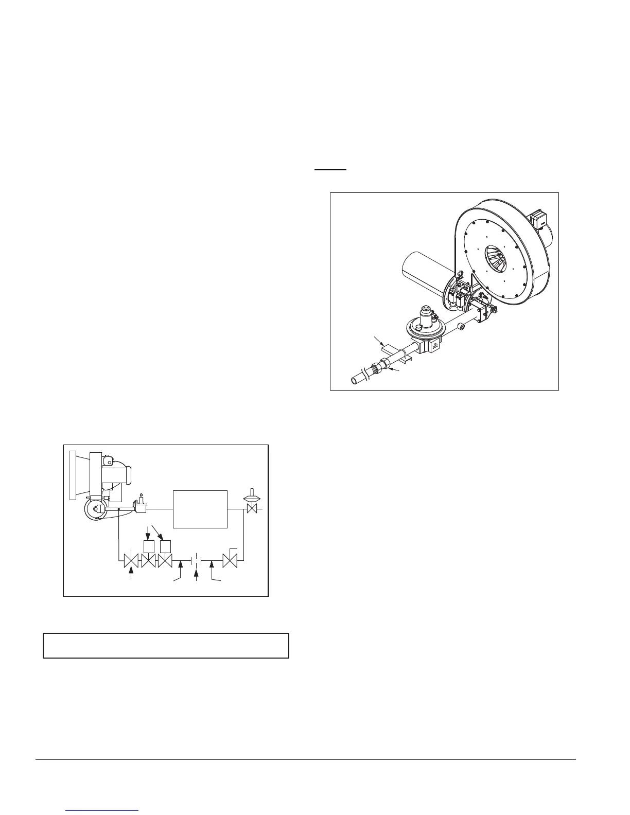
Figure 3.9. Piping Connections
Piping Support
Use brackets or hangers to support the gas piping. If you
have questions, consult your local gas company.
Packaged Blower Motor Support (RM1000 -
RM3000)
Install a control motor to modulate the air butterfly valve if
not previously installed on the burner.
For RatioMatic models RM1000 through RM3000, the
packaged blower motor requires additional support, which
must be supplied by the customer.
NOTE: Be sure the control motor shaft and air butterfly
valve shaft are aligned properly. In some cases washers
may be used as shims (stacked 0, 1, or 2 high) to ensure
proper alignment. Additionally, a flexible coupling can be
used to handle minor misalignment.
NC
NC
Main gas
shut-off
valve train
NOTICE
Bracket
Pipe Union