7
Eclipse RatioMatic Burners, RM Series, V5, Installation Guide 110, 12/3/2014
Checklist Before Installation
Air Supply
Provide an opening in the burner room of at least one
square inch per 4000 BTU/hr (6 cm
2
per 1 kW) to supply
the burner intake with fresh, outdoor, combustion air.
If there are corrosive fumes or materials in the
surrounding air, find an uncontaminated source to supply
air to the burner, or provide a sufficient air filtering system.
Exhaust
Do not allow exhaust fumes to accumulate in the work
area. Provide some positive means for exhausting from
the furnace and the building.
Access
Make sure the burner is installed in such a way to allow
easy access for inspection and maintenance.
Environment
Make sure the local environment matches the original
operating specifications. Check the following items:
• Voltage, frequency and stability of the electrical
power
• Fuel type and supply pressure of the fuel
• Availability of enough fresh, clean combustion air
• Humidity, altitude and temperature of air
• Presence of damaging corrosive gases in the air
• Prevent direct exposure to water
Installing the Flame Sensor
1. Install the flame sensor into the 1/2" NPT opening in the
rear cover.
2. Make sure the flame sensor of a burner is connected to
the electrical circuit for that burner.
■ If you connect the flame sensor of a burner to the
electrical circuit of the wrong burner, you can
cause fires and explosions.
There are two different types of flame sensors; UV
scanner and flamerod.
UV Scanner
The UV Scanner must be compatible to the flame
monitoring control that is used. Refer to the manual of
your selected control for proper selection of the scanner.
Flame Rod
NOTE: Only specific burner sizes with alloy or silicon
carbide combustors can use a flamerod (see specific
burner datasheets).
For detailed information on how to install and connect a
flamerod, refer to Bulletin/Info guide 832.
Installing the Spark Plug
Install the spark plug into the opening in the rear cover.
NOTE: Do not apply any grease to the threads of the
spark plug or bad grounding of the spark plug may occur,
resulting in a weak spark.
■ Adjustments may vary from Eclipse published
values if the flame controls other than those
recommended in the Design Guide are used.
Consult with the engineer who specified the
alternate control for limitations.
Burner Installation
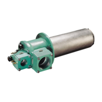
Chamber Opening
Figure 3.1.
Provide an opening in the chamber wall at least 1/2"
(12mm) larger in diameter than the outside diameter of the
combustor, or 1/2" (12mm) larger in height and width than
the square refractory block. (1/4" - 6mm per side).
Provide an accessible pressure tap on the chamber wall
to measure the pressure inside the firing chamber. The
pressure tap should be located near the burner.
Mounting Pattern
Attach mounting bolts to the chamber wall. Position these
bolts to match the clearance holes “C” on the burner
mounting flange. Refer to the appropriate RatioMatic
datasheet.
DANGER
NOTICE
Minimum 1/4" (6mm)
space per side
Combustor
Chamber Wall