12
Eclipse Winnox WX Series v1, Installation Guide No. 111, 8/26/05
Fiber insulation
Chamber
insulation
1
3
2
Combustor
slots
Chamber Wall
Make sure the chamber wall
2
is strong enough to support
the w eight of the burner
3
. If necessary, r einf orce the
mounting area.
n
Note:
The slots in the combustor must not be covered with
insulation. If necessary, taper the chamber insulation at a
minimum of 45° to provide clearance for the combustor
slots.
Burner Mounting
Mount burner to chamber wall using eight (8) customer
supplied nuts and lock washers.
Alloy Combustion Tube
1.
Be sure gasket
1
is installed between burner
3
and
chamber wall
2
.
2.
Pack fiber insulation around the tube to a depth not
beyond the combustor slot position, as illustrated.
c
Caution:
Placing insulation over combustor slots will impede burner
performance and decrease combustor life
3.
No gasket is supplied or required between burner and
combustor.
Figure 3.2 Alloy combustion tube
I
NSTALLATION
(
CONTINUED
)
Combustor
slots
3
2
45 Minimum
Chamber
insulation
Figure 3.1 Chamber wall
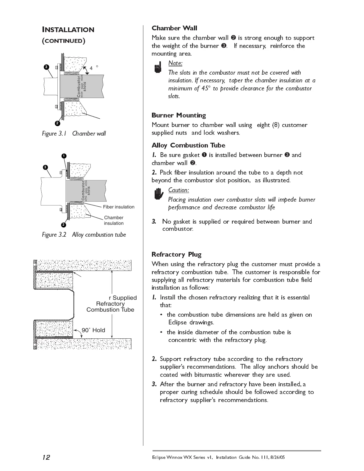
Refractory Plug
When using the refractory plug the customer must provide a
refractory combustion tube. The customer is responsible for
supplying all refractory materials for combustion tube field
installation as follows:
1.
Install the chosen refractory realizing that it is essential
that:
the combustion tube dimensions are held as given on
Eclipse dra wings.
the inside diameter of the combustion tube is
concentric with the refractory plug.
2.
Support refractory tube according to the refractory
suppliers recommendations. The alloy anchors should be
coated with bitumastic wherever they are used.
3.
After the burner and refractory have been installed, a
proper curing schedule should be followed according to
refractory suppliers recommendations.
Fiber
insulation
Customer Supplied
Refractory
Combustion Tube
90˚ Hold
 Loading...