14
Eclipse Winnox WX Series v1, Installation Guide No. 111, 8/26/05
C
HECK
L
IST
A
FTER
I
NSTALLATION
To verify the system was properly installed, perform
the following checks:
1.
Be sure there are no leaks in the gas lines.
2.
Be sure all the components contained in the flame
monitoring and control system are properly installed.
This includes verifying that:
all the switches are installed in the correct
locations.
all wiring, pressure, and impulse lines are properly
connected.
3.
Be sure all components of the spark ignition system are
installed and functioning properly.
4.
Be sure the blower rotates in the proper direction. If the
r otation is incorrect, ha ve a qualified electrician rew i re
the blower to rotate in the proper direction.
5.
Be sure all valves are installed in the proper location and
correctly oriented relative to the flow direction.
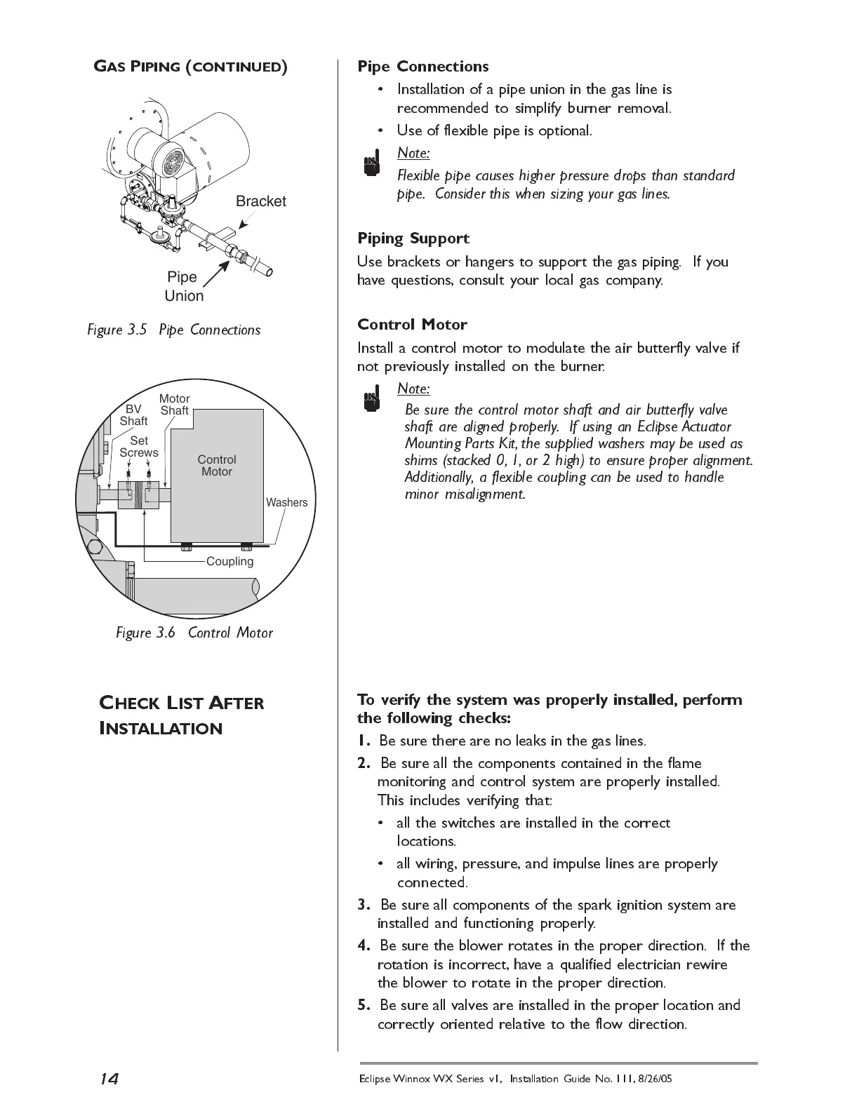
Pipe Connections
Installation of a pipe union in the gas line is
recommended to simplify burner removal.
Use of flexible pipe is optional.
n
Note:
Flexible pipe causes higher pressure drops than standard
pipe. Consider this when sizing your gas lines.
Piping Support
Use brackets or hangers to support the gas piping. If you
have questions, consult your local gas company.
Control Motor
Install a control motor to modulate the air butterfly valve if
not previously installed on the burner.
n
Note:
Be sure the control motor shaft and air butterfly valve
shaft are aligned properly. If using an Eclipse Actuator
Mounting P arts Kit, the supplied w ashers may be used as
shims (stacked 0, 1, or 2 high) to ensure proper alignment.
Additionally, a flexible coupling can be used to handle
minor misalignment.
Figure 3.6 Control Motor
Figure 3.5 Pipe Connections
Pipe
Union
Bracket
Set
Screws
Motor
Shaft
Control
Motor
Coupling
Washers
BV
Shaft
G
AS
P
IPING
(
CONTINUED
)
 Loading...