E C O P H Y S I C S Installation
CLD 780 TR / July 2000 32
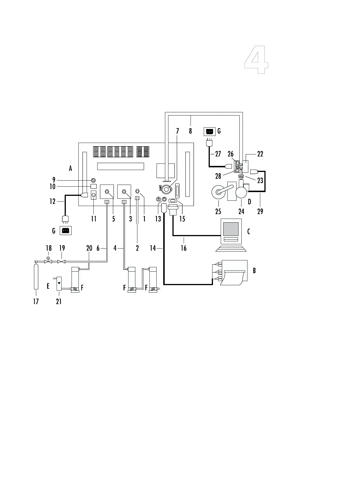
Fig. 4.2
“Installing the CLD 780 TR“
A “ECO PHYSICS CLD
780 TR” NO Analyzer
B Strip-chart recorder
CComputer
D Ozone scrubber & pump
unit
EO
2
supply
F Silica gel drying car-
tridge (lid downward)
G Power outlet 28 VDC
1 Sample Inlet
2 Tubing from sample
source to analyzer
3 Dry air inlet to PMT, with
filter
4 Tubing from silica gel
cartridge to dry air inlet
5O
2
inlet to O
3
generator,
with filter
6Tubing from O
2
source to
analyzer
7 Vacuum connector
8 Vacuum line from ana-
lyzer to O
3
-scrubber-
pump unit
9Main fuse
10 Main switch
11 Power socket
12 Power cable
13 Analog output socket
14 Strip-chart recorder ca-
ble
15 RS 232 D-connector
16 RS 232 interface cable
17 O
2
cylinder
18 2-stage pressure reducer
19 Needle valve
20 T-connector
21 Overflow via flowmeter
22 Ozone scrubber
23 Mounting flange
24 Vacuum pump
25 Pump exhaust filter (e.g.
activated charcoal)
26 Scrubber power switch
with fuse and IEC cable
connector
27 Power cable
28 Aux. power outlet to
vac. pump
29 Power cable (O
3
scrub-
ber to vac. pump)