E C O P H Y S I C S Installation
CLD 780 TR / July 2000 31
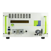
4.2.4 Connecting the CLD 780 TR power and control cables
(see Fig. 4.2).
1. The operator is responsible for the correct supply of power to the in-
strument. Connect the power cable supplied [12] to an external 28
VDC power supply [G] and plug the cable connector into the socket
[11] on the analyzer front panel marked “28 VDC Power”. Remember
the cable polarity: red
→
+ 28 VDC, black
→
0 VDC.
The following peripherals may also be connected to the analyzer:
2. Computer (C) via a serial cable [16] plugged into the 9-pole male D-
type connector [15].
3. Strip-chart recorder via the cable supplied [14] plugged into the ana-
log output connector [13].
Plug color coding:
NO signal: red
NO.c signal: blue
NO
2
signal: yellow
Ground: black