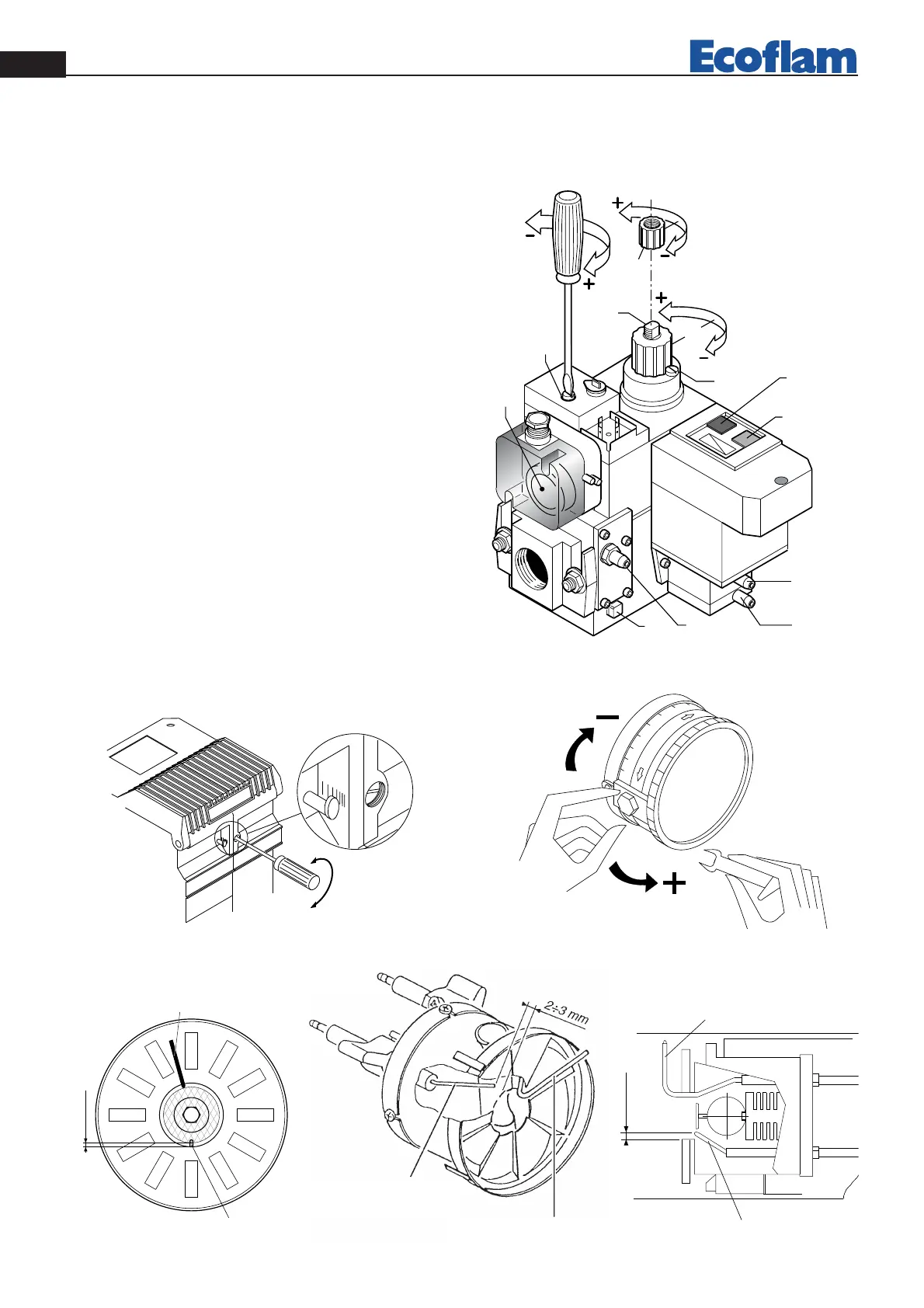
ADJUSTMENT OF FAST OPENING’S HYDRAULIC BRAKE
The adjustment procedure is the same for both single-stage (MB-DLE) and two-stage (MD-ZRDLE) versions.
To adjust the fast opening’s hydraulic brake, unscrew cover T and through its upper side turn pin Q. Screw to reduce
the opening speed; unscrew to increase. Screw cover T after regulation.
pag.6
EN
420010749000 Azur 30/40/60/80 Blu 120 P
AIR REGULATION
ELECTRODE POSITION
AZUR 60
1 Pressure governor adjustment
2 Fast opening hydraulic brake’s adjustment
3 Flow rate adjustment (Low flame flow rate
adjustment for AB version)
4 High flame flow rate adjustment
5 Inlet pressure port
6 Pressure governor membrane’s bleed
7 Minimum presure switch adjustment
(VPS 504)
8 Pressure port after gas filter
9 Pressure port after pressure governor. During leakage control
test, is used to measure test pressure (~150 mbar). When
burner is running, it is used to measure governor’s outlet
pressure.
10 Working lamp (yellow)
11 Leakage control device rearm button (red)