7
www.ecoflam-burners.com
EN
420010372902
Contents - Index - General warnings
Overview
Conformity declaration
3
Technical data 4
Working diagrams 5
Dimensions 6
Contents Index 7
General warnings 7
Burner description 8
Function General safety functions 9
E-BCU GAS control and safety unit 10
Installation Burner assembly 11
Electrical connection 12
Checks before commissioning 12
Start up Adjusting burner output 13
Air pressure switch adjustment - setting gas pressostat 14
Service Maintenance 15
Troubleshooting 16
Overview Gas pressure diagrams 57-58
Electrical diagrams 59
Spare parts list 60-61
Important notes
Ecoflam burners have been designed and
built in compliance with all current
regulations and directives.
All burners comply to the safety
and energy saving operation
regulations within the standard
of their respective performance
range.
The burner must not operate out-
side the working range.
The quality is guaranteed by a quality and
management system certified in
accordance with ISO 9001:2008.
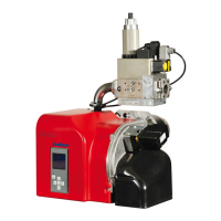
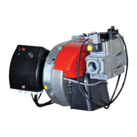
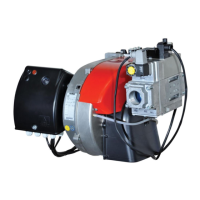
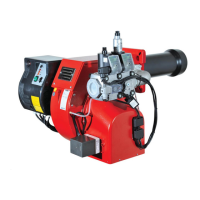
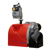
MAX GAS burners are designed
for the low-pollutant combustion of natural
gas and Liquefied Petroleum Gas.
I bruciatori sono conformi alla norma EN
676.
Assembly and commissioning
must be carried out only by
authorised specialists and all
applicable guidelines and
directives must be observed.
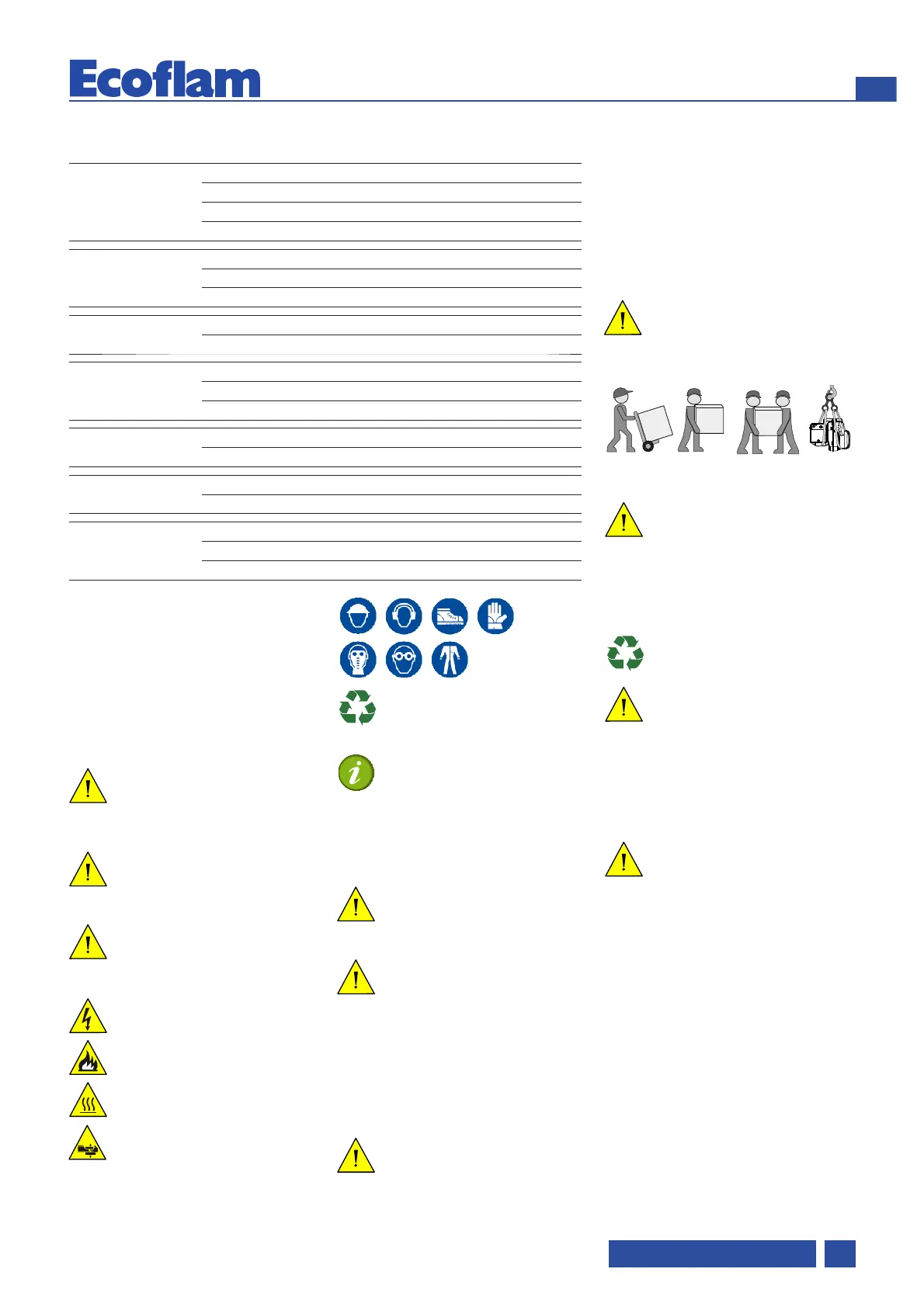
Packaging and handling
Move the burner still in its packaging using
a trolley or forklift, taking care not to drop it
and elevating it no more than 20cm from
ground level. After having removed the
packaging, check that the contents are in
good condition and correspond with what
was ordered. If in doubt, contact the
manufacturer.
The burner must be installed by a
qualified individual.
If the weight and dimensions do not allow
for manual lifting, ask another operator for
help or use a forklift, harness the burner
using belts if no eyebolts are available.
Use the accessories provided
(flange, gasket, pins and nuts) to
install the burner onto the boiler,
taking care not to damage the isolating
gasket.
Installation location
Install the burner, after carefully clean
around the intended area.
correctly dispose of all residual
packaging,separating the various
types of material
The burner must not be operated in
rooms containing aggressive
vapours (e.g. spray,
perchloroethylene, hydrocarbon
tetrachloride, solvent, etc.) or tending to
heavy dust formation or high air humidity.
Adequate ventilation must be provided at
the place of installation of the furnace
system to ensure a reliable supply with
combustion air.
We can accept no warranty
liability whatsoever for loss,
damage or injury caused by any
of the following:
- Inappropriate use.
- Incorrect assembly or repair by the
customer or any third party, including the
fitting of non-original parts.
Provision of the system and the
operating instructions
The firing system manufacturer must
supply the operator of the system with
operating and maintenance instructions on
or before final delivery. These instructions
should be displayed in a prominent
location at the point of installation of the
heat generator, and should include the
address and telephone number of the
nearest customer service centre.
Introduction
The instruction manual supplied with the
burner:
- offers important indications and
instructions relating to the installation
safety, start-up, use and maintenance of
the burner.
- is designed for use by qualified
personnel.
Symbols used in the manual
Maximum danger.
This symbol indicates operations
which cause serious injury, death or
long-term health risks, if not carried
out correctly.
Warning. This symbol indicates
operations which may cause
serious injury, death or long-term
health risks, if not carried out correctly.
Caution. This symbol indicates
operations which may cause
damage to the machine and/or
injury to people, if not carried out
correctly.
Danger: live components
Danger: flammable material
Danger: burning
Danger: crushing of limbs
Obligation to assemble the cover and
all the safety and protection devices.
 Loading...