pag.8
B
LB1007 Minor 20.1/30.1
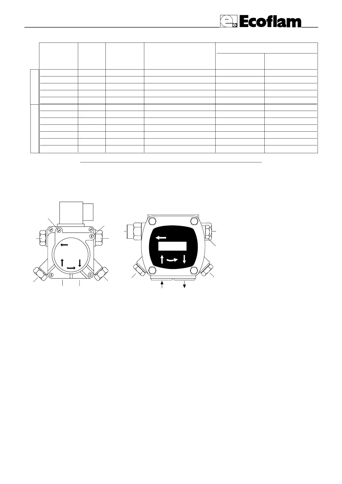
PRIMING AND ADJUSTMENT OF OIL PUMP
1- INLET
2- RETURN
3- BLEED AND PRESSURE
GAUGE PORT
4- VACUUM GAUGE PORT
5- PRESSURE ADJUSTMENT
6- TO NOZZLE
7 - CARTRIDGE FILTER
ADJUSTMENT DATA
NOZZLE : DANFOSS H÷S 80°÷60°; DELAVAN W 60°; STEINEN S 60°
NOZZLE PUMP OUTPUT FIRING HEAD SETTING AIR DAMPER ADJUSTMENT
PRESSURE SIDE SUCTION SIDE
GPH Angolo BAR kg/h POS. Pos. Pos.
2.50 60° 12 10,4 - - MIN
3.00 60° 12 12,5 -
3.50 60° 12 14,9 -
4.00 60° 12 16,7 -
4.50 60° 12 19,1 - - MAX
3.50 60° 12 15,1 1 - MIN
4.00 60° 12 16,7 2
4.50 60° 12 19,1 3 ÷ 4
5.00 60° 12 21,8 4 ÷ 5
5.50 60° 12 23,6 5 ÷ 6
6.00 60° 12 25 6
6.50 60° 12 27,3 7 - MAX
MINOR 20.1-20.1R
MINOR 30.1-30.1R
VERIFY:
- That piping system is perfectly sealed;
- That the use of hoses is avoided whenever is possible (use copper pipes preferably);
- That depression is not greater than 0,45 bar, to avoid pump’s cavitation;
- That check valve is suitably designed for the duty;
The pump pressure is set at a value of 12 bar during the testing of burners. Before starting the burner, bleed
the air in the pump through the gauge port. Fill the piping with light-oil to facilitate the pump priming.
Start the burner and check the pump feeding pressure. In case the pump priming does not take place during
the first prepurging, with a consequent, subsequent lock-out of the burner, rearm the burner’s lock-out to
restart, by pushing the button on the control box. If, after a successful pump priming, the burner locks-out
after the prepurging, due to a fuel pressure drop in the pump, rearm the burner’s lock-out to restart the bur-
ner. Do never allow the pump working without oil for more than three minutes. Note: before starting the
burner, check that the return pipe is open. An eventual obstruction could damage the pump sealing device.
SUNTEC D57 A
Use only the suitable box wrench provided for this operation to remove the nozzle, taking care to not damage
the electrodes. Fit the new nozzle by the same care.
Note: Always check the position of electrodes after having replaced the nozzle (see illustration). A wrong posi-
tion could cause ignition troubles.
NOZZLE CLEANING AND REPLACEMENT
 Loading...