Ecofoot2Plus_Install_Guide_V1.6-FINAL Page 7 of 12
January 5, 2018, ES10560 ecolibriumsolar.com
EcoFoot2+
™
Installation Instructions
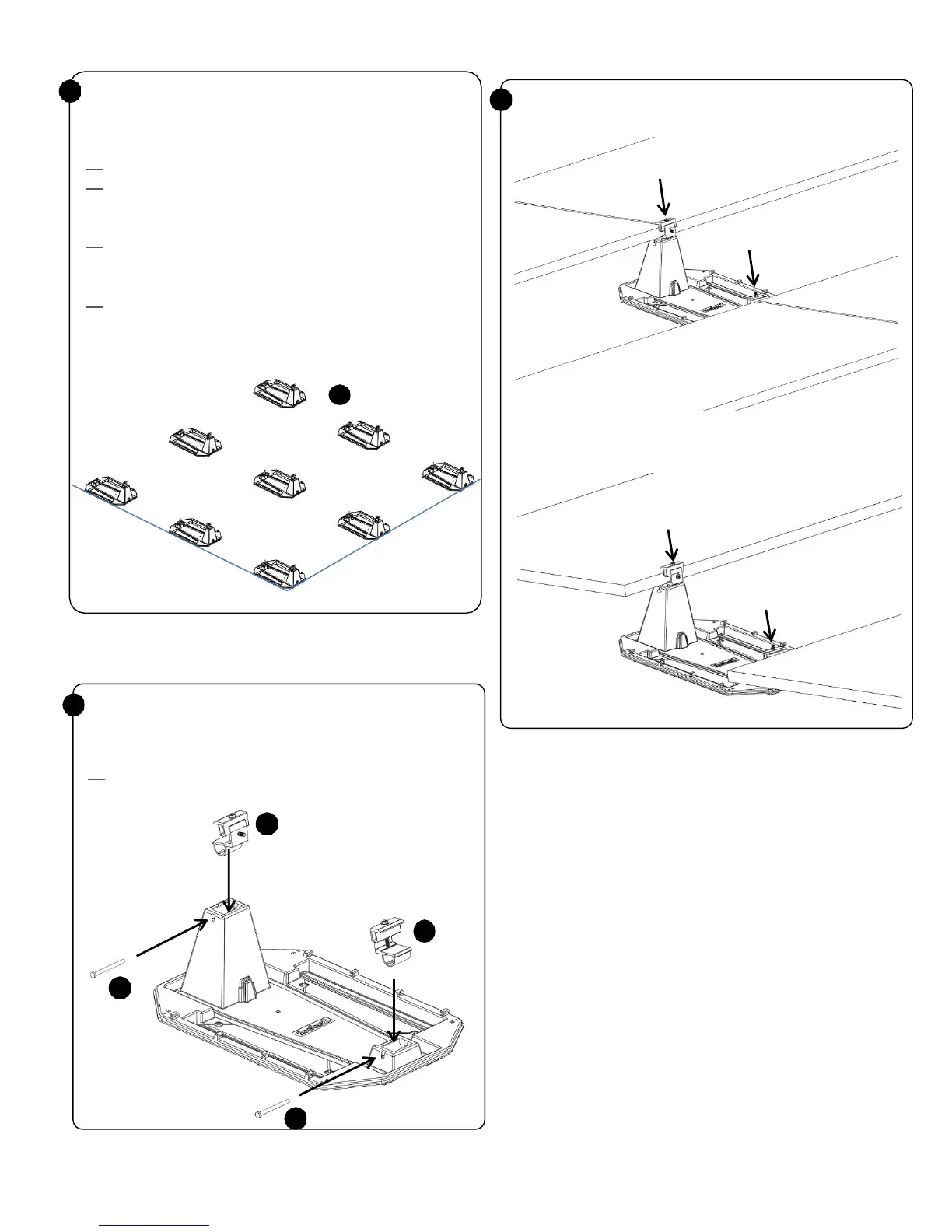
2 Place Lower Clamp (B) and Upper Clamp (C) into
EcoFoot2+ Base (A) as shown. Push Clevis Pin (D)
completely into EcoFoot2+® Base(A) to secure Rocker.
Tip: Only install Clamps where modules will rest. Refer to diagram
below for correct placement and orientation of Clamps.
3
Place module onto EcoFoot2+® Base (A). Using a 1/2"
deep socket, torque Nuts (F) to 1
4 ft-lbs. Space modules
1/2“apart using the alignment marks on the Clamps.
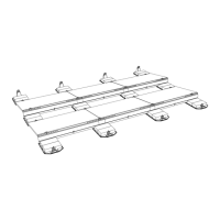
Chalk lines on roof denoting two outside edges of the
EcoFoot2+®
according to project drawing. Place
Bases (A) in position.
: Ensure lines are square using 3-4-5 principle.
: As you
build the array, panels will space Bases. Roughly place
a few rows of Bases at a time so that they are
within r
: If installation requires 2 blocks or fewer on the north row,
Bases can be turned around 180 degrees and tucked
: If installation requires butyl, then butyl will be preinstalled on
Base with protective tape. Ensure these butyl
components are placed where specified in project drawing.
Remove protective tape after step 6.