Installation & Operation Manual Proven Quality since 1892
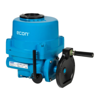
ECON actuator Fig. 7907, type ELA80 – 3000 www.eriks.com
Rev.19 – April 2, 2021 13
4.4 Torque Switch Setting
The torque spring, which detects the variation of torque during the operation, is installed to prevent
damaging the valve and actuator under overload conditions. If an overload of the actuator occurs, the
torque switch will be activated and the actuator stops immediately.
The torque switches are set by manufacturer on the production site. If re-setting is necessary, please
contact the ECON actuator distributer before setting the torque switch.
CAUTION:
Do not reset t he torque switch to a setting higher than the maximum setting
stated by the manufacturer.
4.5 Counter-Clockwise to Close Setting
Standard actuators are normally set to clockwise rotation to close. However, the rotation can be
reversed to counter-clockwise to close by simply reconfiguring the wiring as follows:
• Reverse wiring on the main terminal block: 9 & 10 as well as 11 & 12.
• Adjust the visual indicator to suit the counter-clockwise rotation.
If a PCU card is installed:
• Reverse P1 (orange) and P3 (grey) on the PCU board.
• Move the actuator manually to the half-open position and push the auto-reset button once.
4.6 Mechanical Travel Stop Adjustment
• Loosen both (open and close) travel stopper bolt nuts.
• Operate the actuator manually by turning the hand wheel (the clutch lever must be
switched to “manual” first) to the closed position until the “close” open limit switch is being
activated.
• Tighten the close travel stopper bolt until resistance is felt. (In this position the close travel
stopper bolt should not be able to travel any further).
• Loosen back the close travel stopper bolt by only one turn and tighten the close travel stopper
bolt nut.
• Repeat the same operation for setting of the open travel stopper bolt.
CLOSE TRAVEL
STOPPER BOLT
OPEN TRAVEL
STOPPER BOLT