L
the PumpPAKrM with
a
call for heating
or cooling.
The
use of
impedance
protected pumps
eliminates
the need for
additional
fusing
on the PumpPAKrM.
VIII.
}AYOLT
CONTROL
CIRCUIT
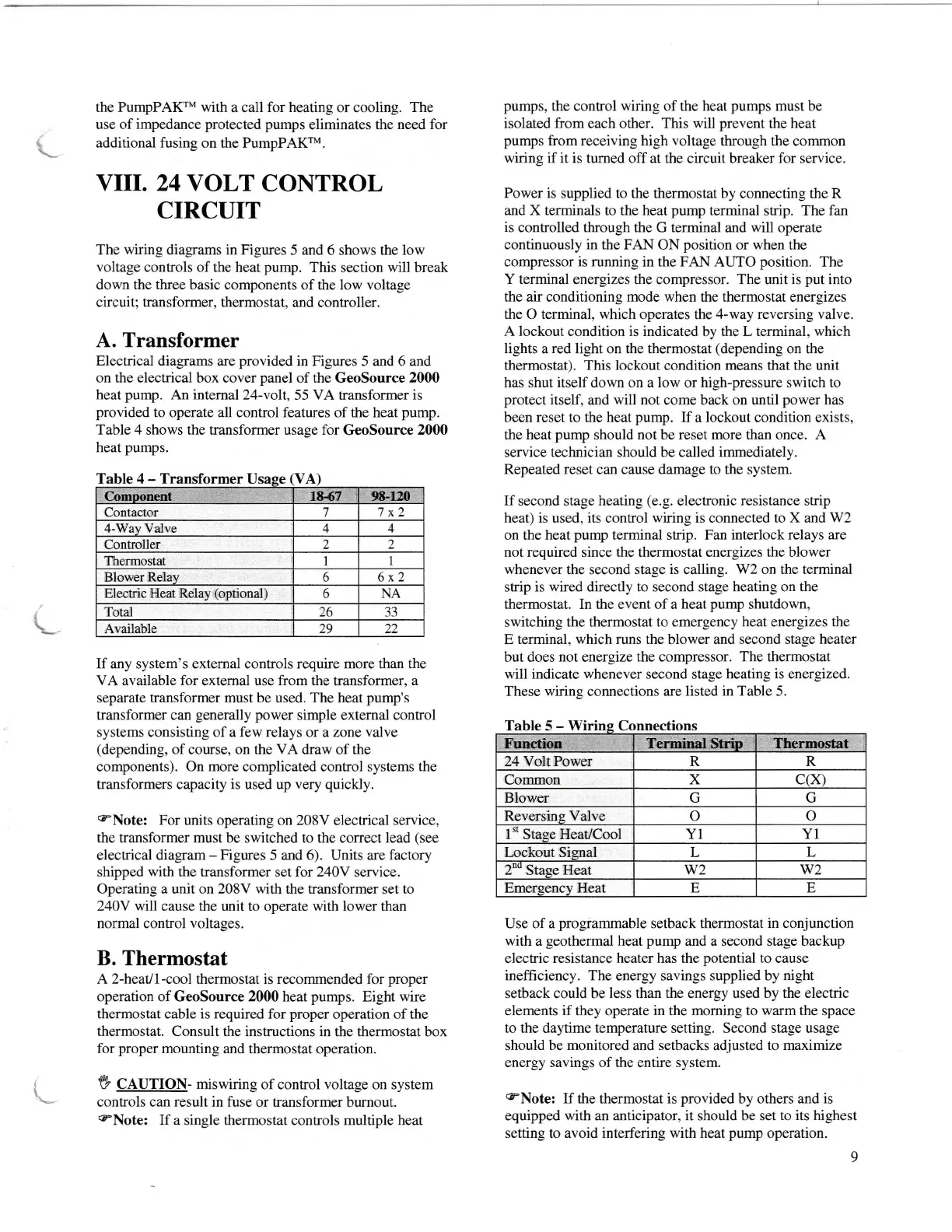
The
wiring
diagrams in Figures 5 and
6 shows the
low
voltage controls of
the
heat
pump.
This section
will
break
down
the three
basic components of the low voltage
circuit; transformer,
thermostat, and controller.
A. Transformer
Electrical diagrams
are
provided
in Figures 5 and 6 and
on
the
electrical box cover
panel
of the
GeoSource
20(X)
heat
pump.
An internal 24-volt,55
VA transformer
is
provided
to operate
all
control features
of the
heat
pump.
Table
4
shows the transformer usase for
GeoSource
2000
heat
pumps.
Table
4
-
Transformer
If any system's external controls require more than the
VA available for
external
use from
the transformer,
a
separate
transformer
must be
used. The
heat
pump's
transformer can
generally power
simple external control
systems consisting of a few relays or a zone
valve
(depending,
of
course, on
the VA
draw of the
components).
On more
complicated control
systems the
transformers capacity is used up very
quickly.
cNote:
For units operating on 208V
electrical
service,
the transformer must be switched to the
correct
lead
(see
electrical
diagram
-
Figures 5 and 6).
Units
are factory
shipped
with
the transformer set for 240V
service.
Operating a unit on 208V
with
the transformer set to
240V
will
cause the unit to operate with lower than
normal control
voltages.
B. Thermostat
A2-heatll-cool thermostat is recommended for
proper
operation of GeoSource 2fi)0 heat
pumps.
Eight
wire
thermostat cable is required for
proper
operation of the
thermostat. Consult
the instructions in the thermostat box
for
proper
mounting
and
thermostat
operation.
V C.LUffON- miswiring of control voltage on system
controls can
result
in fuse or transformer
burnout.
eNote:
If
a single thermostat controls multiple heat
pumps,
the control wiring of the heat
pumps
must be
isolated from
each other. This
will
prevent
the
heat
pumps
from receiving high voltage
through the common
wiring if it is tumed off at the
circuit breaker
for service.
Power is
supplied
to the thermostat
by connecting the R
and X terminals
to the
heat
pump
terminal strip. The fan
is
controlled through the G terminal
and
will operate
continuously in
the
FAN
ON
position
or
when
the
compressor is
running
in the FAN
AI-ftO
position.
The
Y terminal
energizes the compressor.
The
unit is
put
into
the
air conditioning
mode
when the thermostat energizes
the O terminal, which operates
the
4-way reversing valve.
A lockout condition is indicated
by the
L terminal, which
lights
a
red
light on
the
thermostat
(depending
on the
thermostat). This lockout condition means that the unit
has shut itself
down
on a low
or
high-pressure switch to
protect
itself,
and
will not
come back on
until
power
has
been reset
to the heat
pump.
If a
lockout condition
exists,
the heat
pump
should not be reset more than once. A
service technician should be called immediately.
Repeated reset
can
cause dama-ee to
the
system.
If
second stage heating
(e.g.
electronic
resistance
strip
heat) is used, its control
wiring
is connected to
X
and
W2
on the heat
pump
terminal strip. Fan interlock
relays are
not required
since
the thermostat energizes the blower
whenever
the second
stage is
calling.
W2 on the terminal
strip is wired directly to second stage heating on the
thermostat. In the event of a
heat
pump
shutdown,
switching the thermostat
to emergency heat energizes the
E terminal, which runs the blower and second stage heater
but does
not
energize
the compressor. The thermostat
will indicate whenever second
stage
heating
is
energized.
These wiring
connections are
listed in Table 5.
Table
5
-
Connections
Use of a
programmable
setback thermostat
in
conjunction
with a
geothermal
heat
pump
and a second stage backup
electric resistance heater has the
potential
to
cause
inefficiency. The energy savings supplied by
ni-eht
setback could be
less than the
energy
used by the electric
elements if
they operate
in the moming to warm the
space
to the daytime temperature setting. Second stage usage
should be monitored and setbacks
adjusted
to maximize
energy savings of the entire system.
eNote:
If
the thermostat
is
provided
by others and
is
equipped
with
an anticipator, it should be set to
its highest
setting to
avoid interfering
with heat
pump
operation.
9
Contactor 1
7 x2
4-Way Valve
4
4
Controller
')
2
Thermostat I
1
Blower Relay
6
6x2
Electric Heat Relay
(optional)
6
NA
Total 26
JJ
Available
29 22
R R24 Volt Power
Common x c(x)
Blower G G
Reversing
Valve o o
1"
Stase Heat/Cool Y1
YI
Lockout Sisnal L
L
2oo
Stage
Heat w2 w2
Emergency
Heat
E E
\
L
Comoonent 18{7 98-12{'
Functiog Terminal Strip Tlrermostat