The anticipator has the effect ofreducing
system capacity
by
restricting run
time.
The
thermostat should never be set back to less than 60nF,
Ai-r
temperatures less than
60oF
to the heat
pump
in
residential applications
can cause difficult starting
conditions
and lock the unit
out.
Commercial
applications
can be designed to use lower entering air
temperafures, but 60nF is
a
safe low operating
point
in
residential applications.
C. Controller
The controller receives
a signal
from the thermostat and
initiates
the correct sequence of operation
for
the heat
pump.
The
controller
performs
the following functions:
1) Blower
Operation
2) Earth Loop
Pump lnitiation
3) CompressorOperation
4) 4-Way Valve
Control
5) Compressor Lockouts
6) CompressorAnti-Short-Cycle
7)
System
Diagnostics
8) Overflow Detection
L. Blower
Operation
A signal on the G terminal from the
thermostat to the
controller
will
tell the controller
to ener,eize the blower.
The
controller then energizes
its G output to send control
voltage
directly to the blower
motor relay.
To change blower speeds, move the
wire
on the
fan
terminal strip to the desired setting. Changing
the
speed
from the factory
setting can
cause
problems
with
output
air temperature
or reduced airflow,
locking out the unit.
2.
Earth
Loop Pump Initiation
If a PumpPAKrM is
used, it should
be wired directly to the
contactor of the
compressor.
If a PumpPAKrM is not used,
a sepa.rate
pump
can be used
which is
ener-qized
with
a
pump
relay
(Note:
electrical code
will require a fused
disconnect for
pumps
other than
PumpPAKsrM). When
there is a call for
an Ml output
from the
controller, the
contactor will
energize, starting
the
compressor and earth
loop
pump.
3.
Compressor
Operation
A Yl
signal
from
the thermostat will ask the controller to
initiate heating
or cooling.
The
controller then decides,
based on
lockout
and antishort-cycle
periods,
when
to
bring the
compressor on. The Ml output of the controller
energizes
the compressor. This compressor stays
on until
on the thermostat is
satisfied.
4. 4-Way
Yalve
Control
The
controller energizes
the
4-way reversin-e valve
to
direct the flow
of refrigerant.
When
the thermostat calls
for
cooling on the O terminal, the controller energizes its
O output to send control
power
to the reversing valve
(VR)
to switch the refrigerant
circuit to the cooling mode.
5. Compressor
Lockouts
A
compressor
lockout
occurs
ifthe
high-pressure, low
pressnre
(ia
heating mode), orfreeze
protection pressure
switches open. The controller blocks the signal from the
thermostat to the
contactor that
normally would
energize
the compressor. In the event ofa compressor lockout the
controller
will
send a signal from
L
on the terminal strip
to an LED
on
the
thermostat
to indicate a lockout
condition. This lockout condition
means
that the unit has
shut itself down to
protect
itself, and will not come back
on until
power
has
been disconnected
(via
the circuit
breaker) to the
heat
pump
for one
minute. Problems
that
could cause a lockout
situation
include:
1. Water flow or temperature
problems
2. Air flow or temperature
problems
3.
Internal heat
pump
operation
problems
4. Cold ambient air temperature conditions
tlf a
lockout condition
exists,
the heat
pump
should not
be reset more than once; a service technician should be
called
immediately.
VThe cause
of the lockout must
be
determined.
Repeated reset may cause damage to the
system.
6. Compressor
Anti-Short-Cycle
An anti-short-cycle
is
a delay
period
between the time a
compressor shuts down and
when it is allowed to come on
again. This
protects
the compressor
and avoids nuisance
lockout
conditions.
Anti-short-cycles occur after these
three conditions;
1. A 30 second to one minute
time-out
period
occurs
on the compressor before
it will
start after
its last
shutdown.
2. A four minute 35 second delay
is incorporated into
the timing function immediately after
power
is
applied to the heat
pump.
This
occurs only after
reapplying
power
to the
unit. To avoid this
timeout while servicing the unit, apply
power,
disconnect and reapply
power
very
quickly.
This
can sometimes
eliminate
the waiting
period.
3. A four-minute anti-short-cycle will occur after a
low-pressure switch
opens
in the cooling mode.
This is done to eliminate nuisance lockout
conditions.
If
the compressor
continuously
short
cycles in the cooling mode, shut the thermostat
off
and call
your
service technician.
7.
System
Diagnostics
The
controller
is
equipped
with diagnostic LED lights
which indicate the
system status
at any
particular
time.
The lights indicate
the following conditions:
l. 24Yolt
system
power
GREEN
2. Faultorlockout YELLOW
3. Anti-short-cycle mode RED
8.
Overflow
Detection
An optional overflow detection sensor
may
be added to
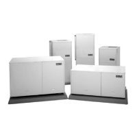
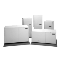
the GeoSource
2000 heat
pumps.
This
sensor
is located
in the drain
pan,
and monitors
the amount of
water
accumulated
in the
pan.
If
the condensate drain becomes
10