CHAPTER 2, INSTALLATION AND OPERATION
98307600 Rev. C-1 2-5
If voltage output is selected, both the REC and DAS outputs are factory-set
for 10 volts full scale. Other full scale outputs of 5 V, 1 V, and 0.1 V can
be selected. Select the full scale output for REC and DAS. When using
voltage output, the source resistance for both REC and DAS outputs is
1000 ohms. The recorder and DAS input resistance should be greater than
500K ohms for a measurement error no greater than 1%.
3. Connect the recorder or DAS wires to the appropriate terminal block. The
wire positions are:
OUT = positive or signal
COM = ground or low
SHLD = shielded cable.
Caution
To prevent ground loop problems, connect the
shield of the cable at the analyzer only, not at the
recorder or DAS.
For additional information regarding output, see section2.6.
2.1.2.1.2 Current Output Connections
When using the EC9830 without the 50-pin I/O PCA, the analyzer still provides
current outputs to drive a strip chart recorder or DAS. These outputs are present
on the discrete I/O connector at the following pins:
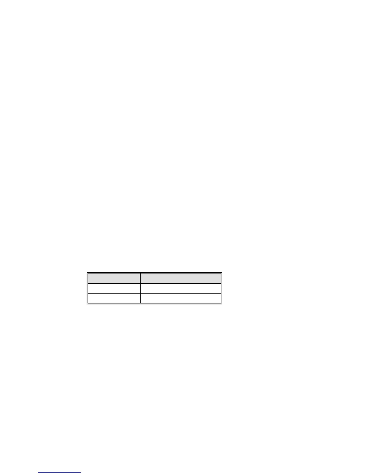
Function Pin (Discrete I/O Connector)
Current Out (+) 15
DGND (Gnd) 1,12,14, or 16
If a current output is connected the range must also be chosen from the menu
when the instrument is operating. The compliance voltage for the current output is
12 V. A terminating resistor of 600 ohms or less should be used for measurement
errors no greater than 1%.
2.1.2.1.3 Voltage Output Connections
The current output mentioned above can be converted to a voltage output by
adding a terminating resistor across the output. This resistor must be 50 ohms per
full scale voltage desired (50 ohms = 1 V full scale; 500 ohms = 10 v full scale,
etc). Following is a list of typical output ranges and required terminating
resistance: