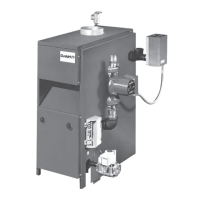
The provided manual describes the Dunkirk PWB Series Gas-Fired Hot Water Boilers, available in both Continuous Pilot (PVWB) and Electronic Intermittent Ignition (PWB) models. These boilers are designed for heating hot water in residential and commercial applications.
Function Description
The Dunkirk PWB Series boilers are gas-fired appliances that heat water for hydronic heating systems. They are equipped with either a continuous pilot or an electronic intermittent ignition system to ignite the main burners. The heated water is then circulated through a piping system to radiation units (e.g., radiators, baseboards, convector radiators) to provide space heating. The system includes safety features such as a safety relief valve, rollout switch, and spill switch to ensure safe operation. A vent damper is integrated to improve efficiency by reducing standby losses when the burner is off.
Important Technical Specifications
The boilers are available in 2 to 9 sections, with varying input MBH, heating capacity MBH, and Net I=B=R Rating MBH.
Input MBH (1,000 Btuh):
- 2-section: 37.5 MBH
- 3-section: 70 MBH
- 4-section: 105 MBH
- 5-section: 140 MBH
- 6-section: 175 MBH
- 7-section: 210 MBH
- 8-section: 245 MBH
- 9-section: 280 MBH
Heating Capacity MBH (D.O.E. test procedure):
- 2-section: 30 MBH
- 3-section: 57 MBH
- 4-section: 85 MBH
- 5-section: 113 MBH
- 6-section: 142 MBH
- 7-section: 170 MBH
- 8-section: 198 MBH
- 9-section: 226 MBH
Net I=B=R Rating MBH (based on 1.15 piping and pickup allowance):
- 2-section: 26 MBH
- 3-section: 50 MBH
- 4-section: 74 MBH
- 5-section: 98 MBH
- 6-section: 123 MBH
- 7-section: 148 MBH
- 8-section: 172 MBH
- 9-section: 197 MBH
Dimensions (Inches):
- Flue Diameter: 3" (2-section), 5" (3-section), 6" (4-5 section), 7" (6-9 section)
- "A" Width: 8" (2-section), 11¼" (3-section), 14½" (4-section), 17¾" (5-section), 21" (6-section), 24¼" (7-section), 27½" (8-section), 30⅝" (9-section)
- Add 5½" to height for vent damper.
Boiler Volume (Cu. Ft.):
- 2-section: 3.8
- 3-section: 5.4
- 4-section: 7.0
- 5-section: 8.5
- 6-section: 10.1
- 7-section: 11.7
- 8-section: 13.2
- 9-section: 14.8
Electrical Supply: Separate 120 volt circuit, 15 ampere, 14 gauge or heavier copper wire.
Thermostat: 24 volt, heat anticipator set at .2 amps.
Gas Pipe Sizes: Refer to tables for Natural Gas and Propane Gas pipe capacity based on length and BTU per hour input.
Altitude Deration: For altitudes above 2,000 ft., input ratings are reduced by 4% for each 1,000 ft.
Usage Features
- Ignition Systems: Available with either a continuous pilot (manual lighting required) or electronic intermittent ignition (automatic lighting).
- Vent Damper: Automatic, motorized stack damper to increase efficiency by reducing standby losses. It closes when the burner is off and fully opens when combustion is required. Can be manually set to "HOLD DAMPER OPEN" for servicing.
- Low Design Water Temperature Systems: For systems below 140°F (e.g., radiant floor heating), a 3-way or 4-way mixing valve (or suitable alternative) must be installed to prevent low temperature return water from entering the boiler.
- Cooling Unit Connection: When used with a refrigeration system, the chilled medium must be piped in parallel with the heating boiler, using appropriate valves to prevent chilled medium from entering the boiler. Flow control valves are required for heating coils in air handling units exposed to refrigerated air circulation to prevent gravity circulation during the cooling cycle.
- Automatic Fill Valve: An optional feature that automatically refills the system as needed, maintaining correct operating water pressure.
- Drain Valve: Manual valve for draining water from the boiler and system.
- Water Temperature Control: Adjustable limit control (140°F to 240°F) to set desired water temperature.
- Circulating Pump: Required for forced hot-water systems, connected to the main just ahead of the boiler and wired to the electrical system.
- Expansion Tank: Conventional or diaphragm type (EX-TROL) to accommodate water expansion and maintain pressure.
- Air Eliminating Fitting (Air Purger): Removes excess air from the system, installed in the supply line.
- Main Air Vent: Speeds up air elimination, especially for down flow systems or with diaphragm type expansion tanks.
Maintenance Features
- Annual Visual Check: Pilot and main burner flames should be checked annually, preferably at the beginning of the heating season.
- Safety Relief Valve Test: Must be tested monthly during boiler operation and at the beginning and end of any extended non-service period. Hold the trip lever fully open for at least five seconds to flush sediment.
- Expansion Tank Maintenance: If waterlogged or overfilled with air (indicated by frequent relief valve opening or low radiation unit temperature with knocking), close the valve to the boiler, drain the tank, check plugs/fittings, and refill.
- Flue Passages, Burner Adjustment, and Controls Check: Recommended annually by a competent Service Technician to ensure trouble-free operation.
- Boiler and Vent Pipe Leak Check: Recheck for leaks before each season or after any shutdown. Replace or patch faulty boiler seals.
- Vent Pipe Inspection: Check at least once a season for leaks and replace immediately if any are found.
- Cleaning Boiler and Burners: Flue passages should be examined and cleaned yearly if necessary. This involves removing burners, pilot, vent pipe, jacket panels, draft diverter, and cerafelt gasket strips. Clean passageways with a wire brush, vacuum dirt, and ensure flame ports are clear. Reseal seams with 400°F RTV silicone sealant.
- Circulator Pump Isolation Valves: Operate manually once or twice a year to prevent sticking.
- Housekeeping: Keep the boiler area clear of combustible materials, flammable vapors, and obstructions to combustion and ventilation air.
- Vent Damper Inspection: Must be inspected at least once a year by a trained service technician. Check indicator points for open/closed positions.
- Troubleshooting Guide: Provides steps for common issues like "System Not Heating," "Burner Is Noisy," and "Relief Valve Leaking."