EasyManua.ls Logo

ECR Dunkirk PWB Series - User Manual

ECR Dunkirk PWB Series
28 pages
Print Icon
To Next Page IconTo Next Page
Loading...
GAS-FIRED
HOT WATER BOILERS
P/N 14683002, Rev. A [8/2011]
PWB SERIES
An ISO 9001-2008 Certified Company
ECR International, Inc.
2201 Dwyer Avenue,
Utica NY 13501
www.ecrinternational.com
MODEL PWB
Electronic
Intermittent Ignition
MODEL PVWB
Continuous Pilot
H
Question and Answer IconNeed help?

Do you have a question about the ECR Dunkirk PWB Series and is the answer not in the manual?

Summary

Dunkirk PWB Series Gas-Fired Hot Water Boilers

Model PVWB: Continuous Pilot Operation

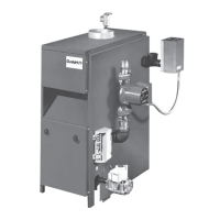
Details the PVWB model with continuous pilot ignition for gas-fired hot water boilers.

Model PWB: Electronic Ignition

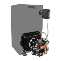
Describes the PWB model featuring electronic intermittent ignition for gas-fired hot water boilers.

Boiler Ratings and Capacities

Natural and Propane Gas Boiler Ratings

Lists input, heating capacity, and net I=B=R ratings for models based on section count.

High Altitude Boiler Performance

Explains input rating reductions for altitudes above 2,000 ft and general guidance for high altitude use.

Pre-Installation Checks and Boiler Location

Initial Setup and Safety Preparations

Covers essential pre-installation checks for gas type, air, electrical, venting, and thermostat placement.

Boiler Placement and Clearances

Guidelines for selecting a boiler location, required clearances, and ventilation needs.

Combustible Material Clearances

Specifies minimum distances from the boiler to combustible materials for safe operation.

Combustion Air Requirements

Ventilation and Combustion Air Methods

Details methods for providing combustion air: indoor air (standard/infiltration) and outdoor air (two/one opening).

Indoor Air Volume Calculation

Provides a table and formula for calculating minimum room volume for indoor air based on input MBH and ACH.

System Piping Installation

Safety Relief Valve Installation Guide

Instructions for installing the safety relief valve and its discharge piping to a drain.

Temperature Pressure Gauge Installation

Steps for correctly installing the temperature pressure gauge onto the boiler's supply water tee.

Piping for Special Systems

Low Temperature Water Systems

Recommends mixing valves for systems below 140°F to prevent low temperature return water.

Boilers with Cooling Units

Guidelines for integrating the boiler with refrigeration systems and air handling units.

Chimney and Vent Pipe Connection

Chimney Inspection and Sizing Requirements

Emphasizes checking chimney condition, size, and construction for proper venting of combustion gases.

Vent Damper Installation Procedures

Details vent damper installation, including placement, fastening, and adapter use for 2-section boilers.

Vent Pipe Clearances and Common Venting

Minimum Vent Pipe Clearance Rules

Specifies the required minimum clearance between single-wall metal vent pipe and combustible materials.

Common Venting System Procedures

Outlines steps for safely removing a boiler from a common venting system and verifying remaining appliances.

Vent Damper Operation and Control

Damper Installation and Functional Checks

Explains how to check vent damper operation and provides instructions for manual control.

Gas Supply Piping Installation

Gas Pipe Sizing and Connection Guidelines

Details sizing gas pipes by length and BTU input, and rules for connecting gas piping to the boiler.

Gas Piping Safety and Testing

Essential safety warnings and procedures for checking gas piping, including leak detection and pressure testing.

Electrical Wiring and Connections

Power Supply and Grounding

Outlines requirements for the 120-volt power supply circuit, including amperage, shut-off, and grounding.

Thermostat and Control Wiring

Guides on thermostat location selection and wiring to aquastat terminals, plus vent damper/circulator wiring.

Intermittent Ignition Wiring Diagram

Intermittent Ignition Control Wiring

Details wiring for intermittent ignition systems: thermostat, aquastat, pilot control, gas valve, and vent damper.

Standing Pilot Wiring Diagram

Standing Pilot Control Wiring

Details wiring for standing pilot systems: thermostat, aquastat, pilot, gas valve, and vent damper.

Boiler Components and Accessories

Key Component Functions Explained

Explains the functions of safety relief valve, expansion tank, air purger, automatic fill valve, drain valve, and temperature control.

Circulator Pump and Vent Damper Roles

Describes the function of the circulating pump for system circulation and the vent damper for efficiency.

Safety Devices and System Startup

Rollout and Spill Safety Switches

Explains the function of the rollout switch (flame rollout) and spill switch (blocked vent).

Boiler System Operation and Filling

Details how a hot-water system operates and the procedure for filling it with water.

Critical Safety and Operating Instructions

General Safety Warnings and Gas Leaks

Provides critical warnings about fire/explosion, smelling gas, and handling submerged appliances.

Intermittent Ignition Boiler Startup

Step-by-step instructions for operating an intermittent ignition boiler, including starting and shutting down.

Continuous Pilot Boiler Operation

Continuous Pilot Startup and Shutdown

Step-by-step guide for operating a continuous pilot boiler, including lighting and shutdown procedures.

Automatic Gas Valve and Safety Pilot Testing

Explains automatic gas valve, safety pilot function, and gas valve safety shutdown test procedures.

Boiler Adjustments and Temperature Settings

Pilot and Main Burner Adjustments

Instructions for adjusting pilot burner flame and checking main burner flame appearance for proper operation.

Limit Control and Water Temperature Settings

Guides on adjusting limit controls and recommended boiler water temperatures for different heating units.

Boiler Maintenance Procedures

Annual Boiler Inspection and Cleaning

Details annual checks for burners, flue passages, vent pipe, and instructions for cleaning the boiler and burners.

Safety Valve Testing and System Care

Covers testing the safety relief valve, managing expansion tank issues, draining the system, and servicing circulator pump valves.

Boiler Service Hints and Troubleshooting

Troubleshooting Heating Performance

Provides potential causes and solutions for common heating issues like thermostat problems, power loss, or poor radiator heat.

Addressing Noisy Burners and Leaks

Offers troubleshooting advice for noisy burners, relief valve leaks, and water-logged expansion tanks.

Repair Parts: Jacket, Section, and Base

Jacket, Section, and Base Components List

Lists part numbers for jacket, section, and base components for various boiler sizes, 2 to 9 sections.

Repair Parts: Burner and Manifold

Burner and Manifold Parts List

Lists part numbers for burner and manifold components, including gas valves, orifices, and pilot burners.

Repair Parts: Boiler Controls and Piping

Controls and Piping Components List

Lists part numbers for boiler controls (aquastats, pilot controls) and various piping fittings and valves.

Overview

The provided manual describes the Dunkirk PWB Series Gas-Fired Hot Water Boilers, available in both Continuous Pilot (PVWB) and Electronic Intermittent Ignition (PWB) models. These boilers are designed for heating hot water in residential and commercial applications.

Function Description

The Dunkirk PWB Series boilers are gas-fired appliances that heat water for hydronic heating systems. They are equipped with either a continuous pilot or an electronic intermittent ignition system to ignite the main burners. The heated water is then circulated through a piping system to radiation units (e.g., radiators, baseboards, convector radiators) to provide space heating. The system includes safety features such as a safety relief valve, rollout switch, and spill switch to ensure safe operation. A vent damper is integrated to improve efficiency by reducing standby losses when the burner is off.

Important Technical Specifications

The boilers are available in 2 to 9 sections, with varying input MBH, heating capacity MBH, and Net I=B=R Rating MBH.

Input MBH (1,000 Btuh):

  • 2-section: 37.5 MBH
  • 3-section: 70 MBH
  • 4-section: 105 MBH
  • 5-section: 140 MBH
  • 6-section: 175 MBH
  • 7-section: 210 MBH
  • 8-section: 245 MBH
  • 9-section: 280 MBH

Heating Capacity MBH (D.O.E. test procedure):

  • 2-section: 30 MBH
  • 3-section: 57 MBH
  • 4-section: 85 MBH
  • 5-section: 113 MBH
  • 6-section: 142 MBH
  • 7-section: 170 MBH
  • 8-section: 198 MBH
  • 9-section: 226 MBH

Net I=B=R Rating MBH (based on 1.15 piping and pickup allowance):

  • 2-section: 26 MBH
  • 3-section: 50 MBH
  • 4-section: 74 MBH
  • 5-section: 98 MBH
  • 6-section: 123 MBH
  • 7-section: 148 MBH
  • 8-section: 172 MBH
  • 9-section: 197 MBH

Dimensions (Inches):

  • Flue Diameter: 3" (2-section), 5" (3-section), 6" (4-5 section), 7" (6-9 section)
  • "A" Width: 8" (2-section), 11¼" (3-section), 14½" (4-section), 17¾" (5-section), 21" (6-section), 24¼" (7-section), 27½" (8-section), 30⅝" (9-section)
  • Add 5½" to height for vent damper.

Boiler Volume (Cu. Ft.):

  • 2-section: 3.8
  • 3-section: 5.4
  • 4-section: 7.0
  • 5-section: 8.5
  • 6-section: 10.1
  • 7-section: 11.7
  • 8-section: 13.2
  • 9-section: 14.8

Electrical Supply: Separate 120 volt circuit, 15 ampere, 14 gauge or heavier copper wire. Thermostat: 24 volt, heat anticipator set at .2 amps. Gas Pipe Sizes: Refer to tables for Natural Gas and Propane Gas pipe capacity based on length and BTU per hour input. Altitude Deration: For altitudes above 2,000 ft., input ratings are reduced by 4% for each 1,000 ft.

Usage Features

  • Ignition Systems: Available with either a continuous pilot (manual lighting required) or electronic intermittent ignition (automatic lighting).
  • Vent Damper: Automatic, motorized stack damper to increase efficiency by reducing standby losses. It closes when the burner is off and fully opens when combustion is required. Can be manually set to "HOLD DAMPER OPEN" for servicing.
  • Low Design Water Temperature Systems: For systems below 140°F (e.g., radiant floor heating), a 3-way or 4-way mixing valve (or suitable alternative) must be installed to prevent low temperature return water from entering the boiler.
  • Cooling Unit Connection: When used with a refrigeration system, the chilled medium must be piped in parallel with the heating boiler, using appropriate valves to prevent chilled medium from entering the boiler. Flow control valves are required for heating coils in air handling units exposed to refrigerated air circulation to prevent gravity circulation during the cooling cycle.
  • Automatic Fill Valve: An optional feature that automatically refills the system as needed, maintaining correct operating water pressure.
  • Drain Valve: Manual valve for draining water from the boiler and system.
  • Water Temperature Control: Adjustable limit control (140°F to 240°F) to set desired water temperature.
  • Circulating Pump: Required for forced hot-water systems, connected to the main just ahead of the boiler and wired to the electrical system.
  • Expansion Tank: Conventional or diaphragm type (EX-TROL) to accommodate water expansion and maintain pressure.
  • Air Eliminating Fitting (Air Purger): Removes excess air from the system, installed in the supply line.
  • Main Air Vent: Speeds up air elimination, especially for down flow systems or with diaphragm type expansion tanks.

Maintenance Features

  • Annual Visual Check: Pilot and main burner flames should be checked annually, preferably at the beginning of the heating season.
  • Safety Relief Valve Test: Must be tested monthly during boiler operation and at the beginning and end of any extended non-service period. Hold the trip lever fully open for at least five seconds to flush sediment.
  • Expansion Tank Maintenance: If waterlogged or overfilled with air (indicated by frequent relief valve opening or low radiation unit temperature with knocking), close the valve to the boiler, drain the tank, check plugs/fittings, and refill.
  • Flue Passages, Burner Adjustment, and Controls Check: Recommended annually by a competent Service Technician to ensure trouble-free operation.
  • Boiler and Vent Pipe Leak Check: Recheck for leaks before each season or after any shutdown. Replace or patch faulty boiler seals.
  • Vent Pipe Inspection: Check at least once a season for leaks and replace immediately if any are found.
  • Cleaning Boiler and Burners: Flue passages should be examined and cleaned yearly if necessary. This involves removing burners, pilot, vent pipe, jacket panels, draft diverter, and cerafelt gasket strips. Clean passageways with a wire brush, vacuum dirt, and ensure flame ports are clear. Reseal seams with 400°F RTV silicone sealant.
  • Circulator Pump Isolation Valves: Operate manually once or twice a year to prevent sticking.
  • Housekeeping: Keep the boiler area clear of combustible materials, flammable vapors, and obstructions to combustion and ventilation air.
  • Vent Damper Inspection: Must be inspected at least once a year by a trained service technician. Check indicator points for open/closed positions.
  • Troubleshooting Guide: Provides steps for common issues like "System Not Heating," "Burner Is Noisy," and "Relief Valve Leaking."

ECR Dunkirk PWB Series Specifications

General IconGeneral
BrandECR
ModelDunkirk PWB Series
CategoryBoiler
LanguageEnglish

Related product manuals