Do you have a question about the ECR Utica Keystone UH3KWC0.80 and is the answer not in the manual?
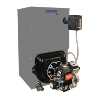
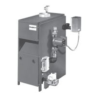
The Keystone Oil-Fired Cast Iron Hot Water Boiler is a natural draft oil-fired hot water boiler designed for residential heating systems. It is available in 3, 4, or 5 cast iron sections, which are held together by cast iron push nipples. The boiler is capable of firing #2 fuel oil at rates ranging from 0.80 gph to 1.55 gph. Packaged boilers come equipped with a swing door, a Hydrolevel limit control with a built-in low water cutoff, a temperature and pressure gauge, a safety relief valve, a drain valve, a flue brush, and an extra boiler tap for an expansion tank or air elimination. These low-pressure hot water boilers are constructed and hydrostatically tested for a maximum working pressure of 50 psig, in accordance with ASME Boiler and Pressure Vessel Code Section IV Standards.
The heating capacity of the boiler indicates the amount of heat available after accounting for stack losses, with most of this heat being used to heat water. A small portion of heat from the jacket and boiler surface is assumed to remain within the structure. The Net AHRI Rating represents the portion of remaining heat that can be applied to radiation or terminal units, such as finned tube baseboard, cast iron radiators, or radiant floor systems. The difference between the Heating Capacity and Net AHRI Rating, known as the piping and pickup allowance, accounts for the reserve needed for the heating system's water volume and to offset heat losses from system piping. It is crucial that the Net AHRI Rating of the selected boiler meets or exceeds the calculated peak heating load (heat loss) for the building or area it serves. For installations with unusual piping or pickup requirements, consulting the manufacturer before selection is recommended.
For safe installation and operation, several safety notices must be observed. The combustion chamber insulation contains ceramic fiber material, which can convert to cristobalite at high temperatures. Crystalline silica, when inhaled, is carcinogenic. Therefore, it is essential to avoid breathing dust and contact with skin and eyes by using a NIOSH-certified dust respirator (N95), long-sleeved clothing, gloves, and eye protection. Water should be applied to the combustion chamber lining to prevent dust, and contaminated clothes should be washed separately. In case of eye contact, irrigate immediately, and for breathing issues, seek fresh air.
The boiler must only use #2 fuel oil. Using gasoline, kerosene, crankcase oil, or any oil containing gasoline is prohibited due to fire, explosion, burn, and scald hazards. Improper installation can lead to serious injury or death. The boiler is designed for residential installations, and for commercial applications, all jurisdictional requirements, including potential wiring and piping modifications, must be met. The manufacturer is not responsible for changes to the original design.
Before servicing, the boiler must be allowed to cool, and all electricity and oil supply must be shut off. Oil lines and connections should be inspected for leaks. The oil burner nozzle size must be verified, as over-firing can cause premature boiler section failure and dangerous operation. The boiler must always be vented to the outside and never into an enclosed space or another room. Adequate air supply for complete combustion is essential, and a regular service and maintenance schedule should be followed for efficient, safe, and reliable operation. The boiler area must be kept clean and free of combustible materials, gasoline, and other flammable vapors and liquids. Oil burners are not DIY items and must be installed and serviced by qualified professionals using combustion test instruments.
A significant burn and scald hazard exists from the safety relief valve discharging steam or hot water during operation. Discharge piping must be installed according to instructions. If the system pressure exceeds 30 psig, the safety relief valve will automatically open, discharging large quantities of steam and hot water, which can cause damage. Before installing the safety relief valve, the manufacturer's instructions and maintenance section should be reviewed.
Proper installation and sizing of the expansion tank are critical, considering the heating system's total water volume, temperature, initial boiler fill pressure, and system arrangement. Incorrectly installed or sized expansion tanks can lead to frequent safety relief valve lifting or other heating system problems. Manufacturer guidelines for expansion tank sizing and selection should be followed. Overfilling the boiler can hinder expansion tank performance and life expectancy. An initial fill pressure of 10-12 psig is recommended, and for higher fill pressures, the expansion tank's air charge must be increased accordingly.
Purging air and gases from the heating system when first placing the boiler into service is essential for proper circulation and quiet performance. Once purged, float-type air vents should be closed for normal operation. If air is detected or heat loss occurs, the system should be purged, and vents opened for a short period.
The boiler should be located centrally to the piping system and as close to the chimney as possible. It must be level, using metal shims if necessary. A raised base is recommended if the floor might become wet or damp. Clearances for fire safety and servicing must be maintained: 18" at a side for access, 6" from combustible material on the left side, rear, and above, and 24" on the right side and front. A 24" accessibility clearance above the boiler is also required for servicing. Fresh air for combustion and ventilation must be available at the front and rear of the boiler, with air passages kept free of obstructions. The floor supporting the boiler must be noncombustible and stable. If placed on a combustible floor, it must be protected according to accepted building code practice and approved by the Authority Having Jurisdiction, or NFPA-31 Standard for the Installation of Oil-Burning Equipment.
Adequate fresh air for combustion is crucial. If the boiler is in an unconfined space (e.g., an open basement), air leakage through cracks around doors and windows is usually sufficient. However, in a confined space, two permanent openings communicating with additional room(s) or outdoors are required. These openings must have a minimum free area of one square inch per 1,000 Btu per hour of total input rating of all combustion equipment, with a minimum of 100 square inches. For example, a total input of 130,000 Btu/hr would require two grilles, each with 130 square inches of free opening. Metal grilles typically have about 60% free opening, so a louvered area of 221.0 sq. in. (130 x 1.7) would be needed, resulting in two 8" x 30" grilles.
For all air from outdoors, confined spaces need two permanent openings: one within 12 inches of the top and one within 12 inches of the bottom of the enclosure. These openings can communicate directly with outdoors or through ducts. Direct communication requires one square inch per 4,000 Btu/hr of total input. Vertical ducts also require one square inch per 4,000 Btu/hr. Horizontal ducts require one square inch per 2,000 Btu/hr. Ducts must have the same cross-sectional area as the openings they connect to, with a minimum dimension of three inches for rectangular ducts.
The installation of the boiler for a new heating system involves first installing all radiation units and supply/return mains. After all system piping is in place, the final connection to the boiler is made. It is recommended to mount the circulating pump on the supply side, pumping away from the expansion tank. Hot water boilers installed above radiation level must have a low water cutoff device, which requires periodic inspection and flushing of float-type devices.
Packaged boilers come with 1¼" NPT supply and return piping at the front, which can be moved to the rear. However, the return line should not be piped to the front, nor the supply line to the rear, to avoid short-circuiting the heat exchanger. A drain valve is provided in the return tee. The safety relief valve is installed in the rear section using a ¾" nipple and street elbow, with the spindle in a vertical position. No shutoff valve should be installed between the boiler and the safety relief valve. Discharge piping for the safety relief valve must be ¾" or larger, suitable for temperatures of 375°F (191°C) or greater, and independent of other discharge piping. The piping should be as short and straight as possible, terminating with a plain end, and unions/elbows should be installed close to the valve outlet.
A clean cold water supply is necessary when connecting to the pressure reducing valve. A sand or pump strainer should be used if the water supply is from a well. For low design water temperature systems (below 140°F) and large water content systems, significant condensation can occur if the boiler operates with return temperatures below 120°F, leading to corrosion and damage. A minimum return water temperature of 120°F is recommended. For systems requiring water temperatures below 140°F, a 3-way or 4-way mixing valve or a bypass piping arrangement (as shown in Figure 7) is needed to prevent low-temperature return water from entering the boiler. For large water content systems, a bypass piping arrangement is also suggested.
The boiler is filled by closing the main shutoff valve, isolation valves, and zone valves (if applicable). If bypass piping is installed, the throttling valves should also be closed. The boiler service shutoff valve and balancing valves to each heating zone should be fully open. Then, the drain valve for power purging, isolation valves before and after the boiler circulator, both throttling valves, and the fill line shutoff valve are opened in order. Water will fill the bypass piping, pushing air out through the power purging drain valve. Once air-free, the bypass piping throttling valve is closed. This process is repeated for each heating zone. After all zones are filled and purged, the power purging drain valve and fill line shutoff valve are closed, the main shutoff valve is opened, and the throttling and balancing valves are adjusted.
Alternatively, for filling, all air vents on radiation units are closed, and valves to radiation units are opened. The boiler drain valve, expansion tank drain cock, and air bleed screw on the expansion tank drain fitting must be closed. The fill valve on the piping to the expansion tank and the water inlet to the boiler are opened. The air vent on the lowest radiation unit is opened, and once water flows, it is closed. This process is repeated for each radiation unit, moving to the highest. If automatic vents are present, manual venting is not strictly necessary but speeds up the process. The initial fill pressure should be 10-15 psig. Any pressure drop indicates a leak, which the automatic fill valve should compensate for; if not, the valve should be manually opened.
Tankless coils, if factory packaged, provide instantaneous domestic hot water for intermittent draws. The Hydrolevel Control, a combination high limit/low limit control, is located on the tankless coil cover plate. A tempering valve (mixing valve) is recommended, and a flow restrictor may be needed on the tankless coil inlet piping to match flow rates with boiler heat input. Tankless coils should not be used if the water is excessively hard, as lime or other deposits will accumulate.
Antifreeze, if used, must be nontoxic and specifically intended for closed hydronic heating systems. Automotive antifreeze is prohibited. Antifreeze can reduce boiler capacity by 10% or more and increase fuel consumption. Tankless coil performance decreases with higher antifreeze concentrations.
For oil-fired boilers, vent installations must comply with NFPA-31 Standard for the Installation of Oil-Burning Equipment and local building codes. Proper ventilation is crucial for venting. The chimney must be checked for proper size, construction, and condition. Sidewall venting with a listed power venter is not approved for direct horizontal venting. A listed power venter providing mechanical draft may be used if approved by the Authority Having Jurisdiction, matching the boiler's BTU per hour input.
The chimney connector and draft regulator are essential. A 6" diameter chimney connector pipe and a manufacturer-provided draft regulator are required. The regulator, when properly installed, automatically controls the draft and should be installed as close as practicable to the boiler, preferably in the horizontal section of the pipe. The "top" of the regulator must be at the top, and the short pipe section holding the vane must be horizontal. The chimney connector should start at the boiler with a vertical pipe, then an elbow, and then the draft regulator horizontally. The two sections are joined with a draw-band, and the horizontal pipe must slope up toward the chimney at least ¼ inch per linear foot. The chimney connector must not leak and must be firmly supported, with each section joined by at least two sheet metal screws and every second section supported by a stovepipe wire.
Electrical connections must be made with the electrical power supply turned OFF at the service panel to prevent electrical shock. A 24 Volt thermostat (not provided) should be installed in a proper location, five feet above the floor on an inside wall, sensing average room temperature, avoiding hot spots (concealed pipes, fireplace, TV sets, radios, lamps, direct sunlight, kitchens) and cold spots (concealed pipes or ducts, stairwells drafts, doors drafts, unheated room on other side of wall). The boiler must be permanently grounded according to local codes and the National Electrical Code, using 14 gauge or heavier copper wire to a grounded connection in the service panel or a properly driven ground rod. A 120-volt electrical supply is connected to L1 and L2 terminals, and two thermostat wires to T and T terminals on the Hydrolevel limit control. A separate circuit with a minimum 15-ampere overcurrent protection device is required, and a shutoff switch should be located at the boiler. For packaged boilers, oil burners are factory wired.
The Hydrolevel 3250-Plus temperature limit and operating control are factory set with a high limit of 190°F and a low limit of OFF for cold start boilers without tankless coils. For models with tankless coils, the low limit dial is turned clockwise to the desired temperature. Limit settings can be varied but must be at least 10°F less than the high limit. The economy feature is factory set to 1 for single-zone systems and can be adjusted per Hydrolevel instructions. The low water cut-off feature is factory set to automatic mode, with manual reset or disable options available.
For maintenance, the burner should not be started if excess oil has accumulated, the unit is full of vapor, or the combustion chamber is very hot, due to burn and scald hazards. Annually, a trained Service Technician should check flue passages, the combustion chamber area (target wall, fire door insulation, durablanket), burner adjustment, control operation, and boiler seals (fire door gasket, silicone seal, cast iron sectional seals, flue collector). Before each heating season, the entire system should be rechecked for water, oil, and vent piping leaks, replacing or patching any faulty leaks or seals. The vent pipe should be visually inspected monthly for leakage, deterioration, or soot buildup, and replaced or cleaned as necessary.
The safety relief valve should open automatically if system pressure exceeds 30 psi. If it fails, the system must be shut down, drained, and the valve replaced by a Service Technician. The valve should be tested monthly during the heating season by holding the trip lever fully open for at least five seconds to flush sediment. Conventional expansion tanks may become waterlogged or receive excess air, indicated by frequent safety relief valve opening or high boiler temperature with low radiation unit temperature and "knocking" noises. To correct, close the valve between the boiler and tank, drain the tank, check and tighten all plugs and fittings, then reopen the valve. Diaphragm expansion tanks exhibiting these symptoms should be replaced. If the system is out of service during freezing weather, it must be drained completely to prevent pipes and the boiler from cracking.
The tankless coil (or cover plate) gasket should be checked for leakage at least twice a year and replaced if necessary, ensuring the ten nuts are torqued in an alternating pattern for an equal force and good seal. The control well should be removed every five years, cleaned of scale or sediment, and reinstalled with pipe sealing compound (Teflon tape is not recommended).
Oil burner maintenance, preferably annually before the heating season, includes:
Never burn garbage or paper in the unit, and never leave combustible material around it.
For oil boiler cleaning, shut off all electrical power and fuel oil supply. Remove the vent pipe, inspect it and the chimney for corrosion or deterioration, and clean the chimney base. Replace the vent pipe if damaged. Remove the top jacket panel screws and brass wing nuts holding the flue collector top. Inspect and replace the flue collector gasket if necessary. Before cleaning flue passageways, ensure the combustion chamber blanket is covered. Remove soot from fireside surfaces by brushing diagonally through flue passages, using a drill with a cut-off flue brush end, being careful not to damage the target wall. Vacuum soot from the combustion chamber, again being careful not to damage refractory or blanket insulation. Access the combustion chamber by closing the fuel oil line shutoff valve, disconnecting the fuel oil line, and removing the oil burner and fire door. Inspect the target wall, fire door refractory, and combustion chamber blanket for cracking or deterioration, replacing them if needed. Inspect the door's braided gasket for wear and damage, replacing it with the same material and size. Finally, inspect and clean the oil burner.
Important operating and maintenance requirements include keeping the boiler and its area clean, never burning refuse or any material other than specified fuel, and having the boiler checked annually by a qualified technician.
For troubleshooting, if the system is not heating, check if the thermostat is set correctly (reset if needed), if the burner is operating properly (check flame color and contact service technician if abnormal), if there is electric power to the boiler (check over-current protection and power supply circuit), if controls are out of adjustment (reset), if radiators are heating (open vents, check flow control valve), if the circulating pump is running (check over-current protection, relay operation), if there is poor electrical contact (check terminals and wire joints), and if the chimney flue is blocked (have it professionally cleaned). If the circulator is running when boiler water temperature is below the low limit set point (for tankless coil boilers), confirm the Honeywell L7248L control's ELL parameter is set to ON.
If the relief valve is leaking, check for corrosion and/or deposits on the seat (open valve manually to clear it) or a waterlogged expansion tank (drain tank). For any problems that cannot be corrected, a service technician should be contacted.
| Brand | ECR International |
|---|---|
| Model | UH3KWC0.80 |
| Category | Boiler |
| Fuel Type | Natural Gas |
| Input BTU | 80, 000 BTU/h |
| Output BTU | 64, 000 BTU/h |