11
Chapter 2: Motherboard Installation
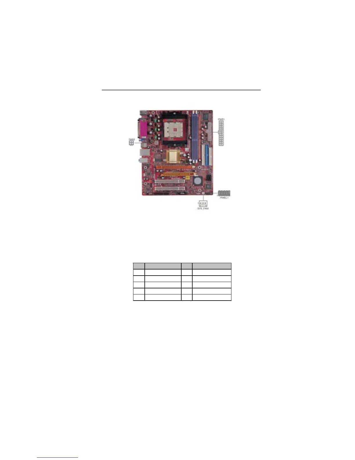
Connect the power connector from the power supply to the PWR1 connector on
the motherboard. PWR2 is a +12V connecotr for CPU Vcore power.
If there is a cooling fan installed in the system chassis, connect the cable from the
cooling fan to the SYS_FAN1 fan power connector on the motherboard.
Connect the case switches and indicator LEDs to the PANEL1 header.
Pin Signal Pin Signal
1 HD_LED_P(+) 2 FP PWR/SLP(+)
3 HD_LED_N(-) 4 FP PWR/SLP(-)
5 RESET_SW_N( - ) 6 POWER_ SW_ P( +)
7 RESET_SW_P( +) 8 POWER_ SW_ N( - )
9 RSVD_DNU 10 KEY
 Loading...