13
Chapter 2: Motherboard Installation
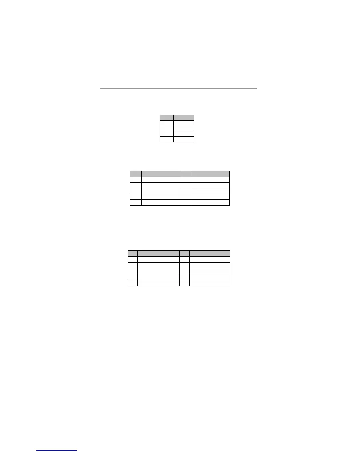
SPK1: Speaker Header
Connect the cable from the PC speaker to the SPK1 header on the motherboard.
F_AUDIO1: Front Panel Audio Header
This header allows the user to install auxiliary front-oriented microphone and
line-out ports for easier access.
Pin Signal
1SPKR
2NC
3NC
4+5V
Pin Signal Pin Signal
1 AUD_MIC1 2 AUD_GND
3 AUD_MIC2 4 AUD_VCC
5 AUD_FPOUT_R 6 AUD_RET_R
7HP_ON 8KEY
9 AUD_FPOUT_L 10 A UD_RET_L
F_USB1/F_USB2: Front panel USB Header
The motherboard has USB ports installed on the rear edge I/O port array.
Additionally, some computer cases have USB ports at the front of the case. If
you have this kind of case, use auxiliary USB headers F_USB1/F_USB2 to
connect the front-mounted ports to the motherboard.
1. Locate the F_USB1/F_USB2 header on the motherboard.
2. Plug the bracket cable onto the F_USB1/F_USB2 header.
3. Remove a slot cover from one of the expansion slots on the system
chassis. Install an extension bracket in the opening. Secure the extension
bracket to the chassis with a screw.
Pin Signal Pin Signal
1 V ERG_FP_ USBPWR0 2 V ERG_FP_ USBPW R0
3 USB_FP_P0(-) 4 USB_FP_P1(-)
5 USB_FP_P0(+) 6 USB_FP_P1(+)
7 GROUND 8 GROUND
9 KEY 10 USB_FP_OC0
 Loading...