23
Installing the Motherboard
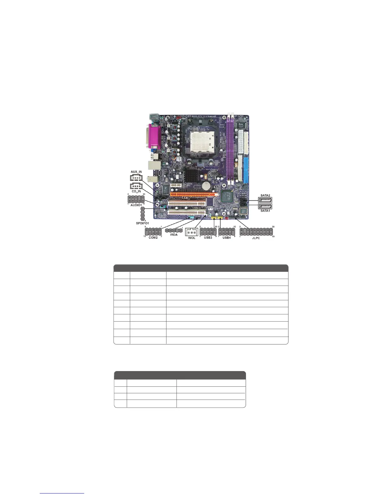
Connecting Optional Devices
Refer to the following for information on connecting the motherboard’s optional devices:
AUDIO1: Front Panel Audio header
This header allows the user to install auxiliary front-oriented microphone
and line-out ports for easier access.
Pin Signal Name
Pin Signal Name Function
1 AUD_MIC Front Panel Microphone input signal
2 AUD_GND Ground used by Analog Audio Circuits
3 AUD_MIC_BIAS Microphone Power
4 AUD_VCC Filtered +5V used by Analog Audio Circuits
5 AUD_F_R Right Channel audio signal to Front Panel
6 AUD_RET_R Right Channel Audio signal to Return from Front Panel
7 REVD Reserved
8 Key No Pin
9 AUD_F_L Left Channel audio signal to Front Panel
10 AUD_RET_L Left Channel Audio signal to Return from Front Panel
SPDIFO1: SPDIF out header
This is an optional header that provides an S/PDIF (Sony/Philips Digital Interface) output
to digital multimedia device through optical fiber or coxial connector.
Pin Signal Name Function
1 SPDIF SPDIF digital output
2 +5VA 5V analog power
3 Key No pin
4 GND Ground
Pin Signal Name
Function
 Loading...