Do you have a question about the ECS G41T-M and is the answer not in the manual?
Introduces the G41T-M motherboard and its high-performance features for desktop markets.
Details processor, chipset, and memory specifications of the motherboard.
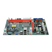
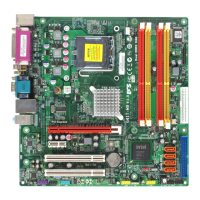
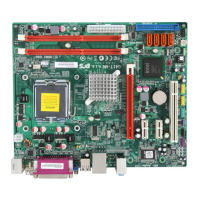
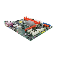
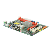
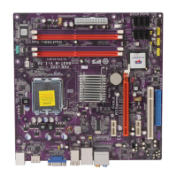
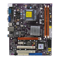
Identifies and lists the various components and connectors on the motherboard.
Outlines essential safety measures to prevent damage during motherboard installation.
Guides on selecting a compatible computer case based on motherboard form factor and requirements.
Provides instructions and considerations for physically mounting the motherboard inside a computer case.
Explains how to set jumpers for correct motherboard configuration.
Covers the installation of essential hardware components like the processor and memory.
Provides detailed steps for installing the CPU and its cooling fan onto the motherboard.
Guides on how to correctly install DDR2 SDRAM modules into the motherboard slots.
Details the types of expansion slots and how to install add-on cards.
Instructions for installing expansion cards into PCI and PCI Express slots on the motherboard.
Details the serial ATA connectors for connecting storage devices.
Explains the front panel audio header for connecting microphone and line-out ports.
Describes front panel USB headers for connecting case USB ports to the motherboard.
Details the analog audio input header for CD-ROM drives.
Explains the SPDIF output header for digital audio devices.
Describes the parallel port header for connecting printers and scanners.
Information about the IDE channel interface and device configuration.
Details the IDE connector for connecting legacy storage devices.
Information about the four SATA connectors for connecting modern storage devices.
Step-by-step guide for installing SATA hard drives using provided cables.
Explains how to connect various I/O devices to the backplane ports.
Instructions for connecting a PS/2 mouse to the motherboard.
Instructions for connecting a PS/2 keyboard to the motherboard.
How to connect serial devices like modems or older mice.
Connecting a monitor to the onboard VGA port.
Connecting to a network via the RJ-45 LAN port.
Connecting various USB devices to the motherboard.
Connecting audio devices to the line-in, line-out, and microphone jacks.
Guides on connecting internal case components to motherboard headers.
How to connect the main 24-pin ATX power supply cable.
How to connect the auxiliary 4-pin ATX12V power cable for CPU power.
Details the pinout and function of the CPU fan power connector.
Provides the pinout and signal assignments for the 24-pin ATX power connector.
Details the pinout and function of the system fan power connector.
Explains the connection and function of the internal speaker header.
Details the pinout and signal assignments for the 4-pin ATX12V power connector.
Describes the front panel header for connecting case switches and LEDs.
How to connect the hard drive activity LED to the front panel header.
Connecting LEDs for power status, sleep, and message waiting indicators.
Connecting the momentary-contact switch for system reset.
Connecting the momentary-contact switch for system power on/off.
Explains the purpose and functionality of the BIOS Setup Utility for system configuration.
Discusses the default system configuration settings available within the BIOS Setup Utility.
Details the procedure to access the BIOS Setup Utility after powering on the system.
Displays basic system information and allows configuration of date, time, and primary drives.
Guides on how to load default BIOS settings to resolve configuration issues.
Configuring IDE and SATA devices for optimal system performance.
Setting the IDE device type for enhanced data transfer.
Optimizing PIO mode for better hard disk performance.
Utilizing DMA for improved transfer speed and data integrity.
Enabling or disabling DMA for IDE devices under DOS mode.
Allows advanced system configuration for CPU, chipset, and boot devices.
Displays CPU temperature and allows setting safe temperature limits.
Shows the status of the Thermal Management function for the CPU.
Enables/disables CPU ID value limit to prevent rebooting issues with certain OS.
Enables or disables the enhanced halt state (C1E) for power saving.
Allows users to enable or disable the Intel XD bit (execute disable).
Enables or disables the Enhanced Intel SpeedStep technology.
Enables hardware virtualization for running multiple virtual machines.
Shortens POST time for faster system startup.
Enables or disables the ECS eJIFFY quick access feature.
Configures advanced chipset settings including DRAM frequency and VGA memory.
Adjusts DRAM frequency; default auto setting is recommended.
Configures DDR timing using SPD data from memory modules.
Allocates main memory portion for onboard VGA display.
Reserves fixed system memory for graphics, according to requirements.
Remaps PCI memory above total physical memory for 64-bit OS.
Enables or disables High Precision Event Timer support.
Sets parameters for system peripheral devices like IDE, SATA, audio, and LAN.
Enables or disables the onboard IDE interface for legacy devices.
Enables or disables the onboard SATA controller for modern storage.
Enables or disables the onboard audio device.
Enables or disables the onboard LAN function for networking.
Enables or disables booting from the onboard LAN or network card.
Assigns port address for the onboard COM1 serial port.
Assigns port address for the onboard Parallel port.
Selects the parallel port mode (Normal, ECP, EPP, Bi-directional).
Assigns DMA channel for ECP Mode function.
Assigns IRQ to the parallel port.
Enables or disables the USB function for peripheral connectivity.
Enables or disables support for legacy USB devices.
Configures system power management settings for suspend modes and wake-up events.
Defines system suspend mode, typically suspend to RAM.
Configures power button behavior for system shutdown and resume.
Enables automatic system restart or status return after power failure.
Allows system to awaken from serial Ring Indicator line signal.
Specifies if system wakes from power saving modes via peripheral activity.
Enables or disables USB device wake-up function from S3/S4 mode.
Enables or disables keyboard activity to awaken system from power saving.
Enables or disables mouse activity to awaken system from power saving.
Allows system to resume at a fixed time based on the system's RTC alarm.
Configures PCI bus parameters and Plug and Play capabilities for installed devices.
Selects the graphics controller to use as the primary boot device.
Monitors critical voltages, temperatures, and fan speeds for system hardware health.
Allows control of CPU fan speed based on temperature and user preferences.
Enables or disables CPU fan speed control via voltage adjustment.
Selects fan operating mode (Normal, Quiet, Silent, Manual) for optimal cooling and noise.
Sets maximum temperature before system shutdown to prevent overheating.
Displays monitoring of system and CPU temperatures, voltages, and fan speeds.
Sets CPU clock speed, system bus, and voltage for performance tuning.
Enables or disables CPU over-clocking functions for performance enhancement.
BIOS disables clock signal for unused DIMM/PCI slots.
Reduces EMI by enabling spread spectrum technology.
Allows setting a supervisor password to protect BIOS configuration.
Indicates if a supervisor password has been set.
Accesses a sub menu to set or change the supervisor password.
Allows setting a user password to restrict system access.
Indicates if a user password has been set.
Guides on downloading and installing updated BIOS for improved performance and fixes.
Describes the contents of the software disc, including drivers and utilities for the motherboard.
Explains the automated process for installing drivers and software on supported Windows operating systems.
Describes how to manually install drivers if the auto-install fails.
Information on the compliance and licensing of available utility software.
Introduces eJIFFY as a fast boot program for instant access to web browsing and other features.
Guides through the process of installing eJIFFY and activating it via BIOS settings.
Provides answers to frequently asked questions about eJIFFY features and usage.
Guides on changing the keyboard language within eJIFFY.
Explains how to access the eJIFFY operating system from the post screen.
Illustrates and describes the main feature icons available in the eJIFFY menu.
Addresses common issues encountered when the PC fails to start after initial assembly.
Discusses common startup issues that arise after extended PC usage.
Provides essential PC care and maintenance advice to prolong motherboard life.
| Number of memory slots | 2 |
|---|---|
| Maximum internal memory | 8 GB |
| Processor socket | LGA 775 (Socket T) |
| Processor manufacturer | Intel |
| S/PDIF out connector | Yes |
| Number of SATA connectors | 4 |
| Number of Parallel ATA connectors | 1 |
| USB 2.0 ports quantity | USB 2.0 ports have a data transmission speed of 480 Mbps, and are backwards compatible with USB 1.1 ports. You can connect all kinds of peripheral devices to them. |
| Firewire (IEEE 1394) ports | 0 |
| Audio chip | VIA VT1708B |
| Power source type | ATX |
| Audio output channels | 5.1 channels |
| Motherboard form factor | micro ATX |
| Graphics card | GMA X4500 |
| Networking features | Fast Ethernet |
| ACPI version | 1.0 |
| BIOS memory size | 64 Mbit |
| Depth | 204 mm |
|---|---|
| Width | 244 mm |