16
Installing the Motherboard
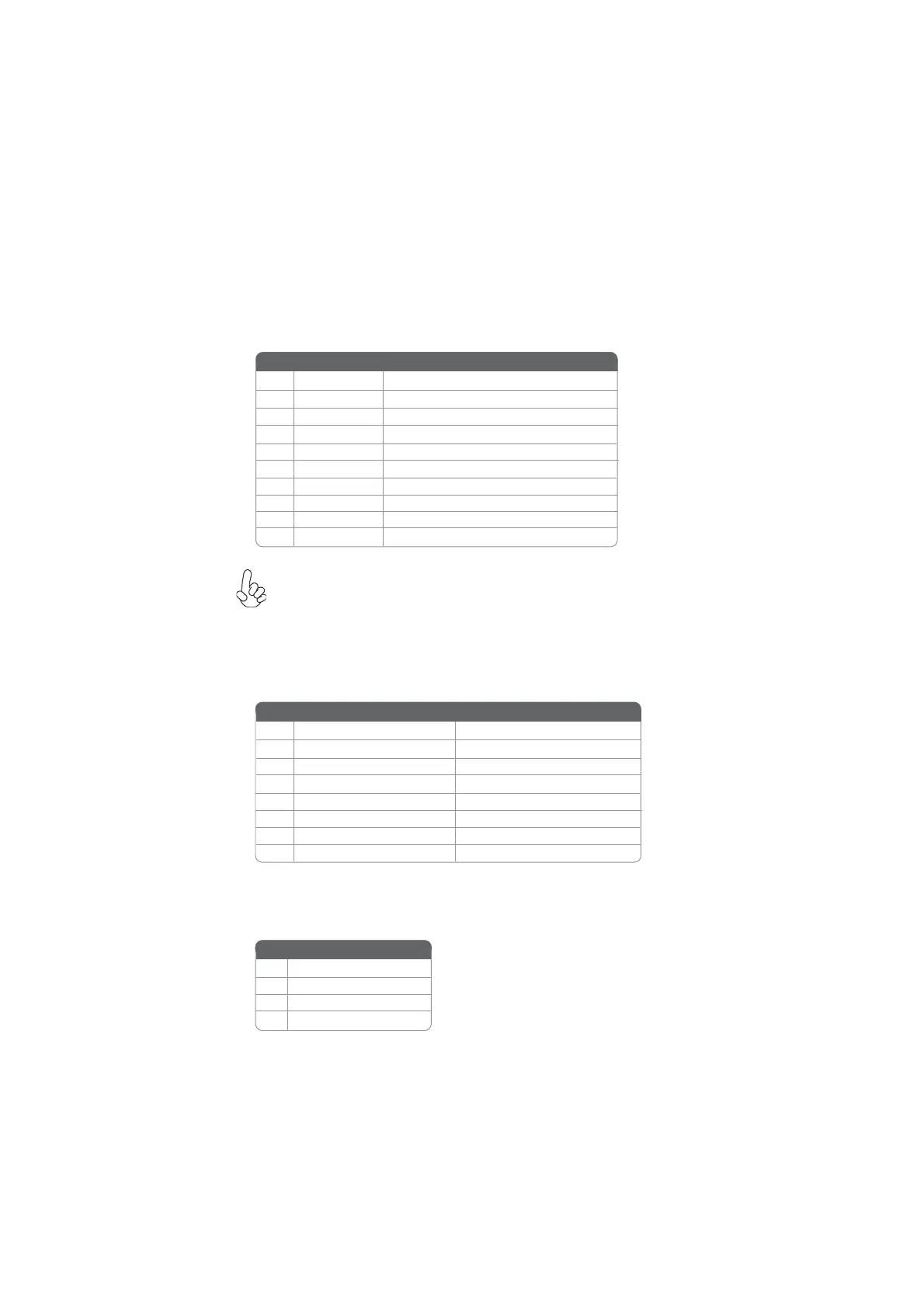
F_USB1: Front Panel USB 2.0 header
The motherboard has one USB 2.0 header supporting two USB 2.0 ports. Addition-
ally, some computer cases have USB 2.0 ports at the front of the case. If you have
this kind of case, use auxiliary USB 2.0 connector to connect the front-mounted
ports to the motherboard.
Please make sure that the USB cable has the same pin assignment as
indicated above. A different pin assignment may cause damage or system
hang-up.
1 USBPWR Front Panel USB Power
2 USBPWR Front Panel USB Power
3 USB_FP_P0- USB Port 0 Negative Signal
4 USB_FP_P1- USB Port 1 Negative Signal
5 USB_FP_P0+ USB Port 0 Positive Signal
6 USB_FP_P1+ USB Port 1 Positive Signal
7 GND Ground
8 GND Ground
9 Key No pin
10 NC Not connected
Pin Signal Name Function
FPD: FPD power connector
The motherboard must provide additional power for the internal flat panel display
(both panel and backlight inverter) via an FPD power connector.
HDD_PW: HDD power connector
This connector is used to provide power for the HDD.
1+12V
2+5V
3 +3.3V
4GND
Pin Signal Name
6 BKLT_GND/Brightness_GND Ground (shared)
7 Brightness_UP Panel brightness increase
1 BKLT_EN Backlight enable
2 BKLT_PWM Backlight control
3 BKLT_PWR Backlight inverter power
4 BKLT_PWR Backlight inverter power
5 BKLT_GND/Brightness_GND Ground (shared)
8 Brightness_DOWN Panel brightness decrease
Pin Signal Name Function
 Loading...