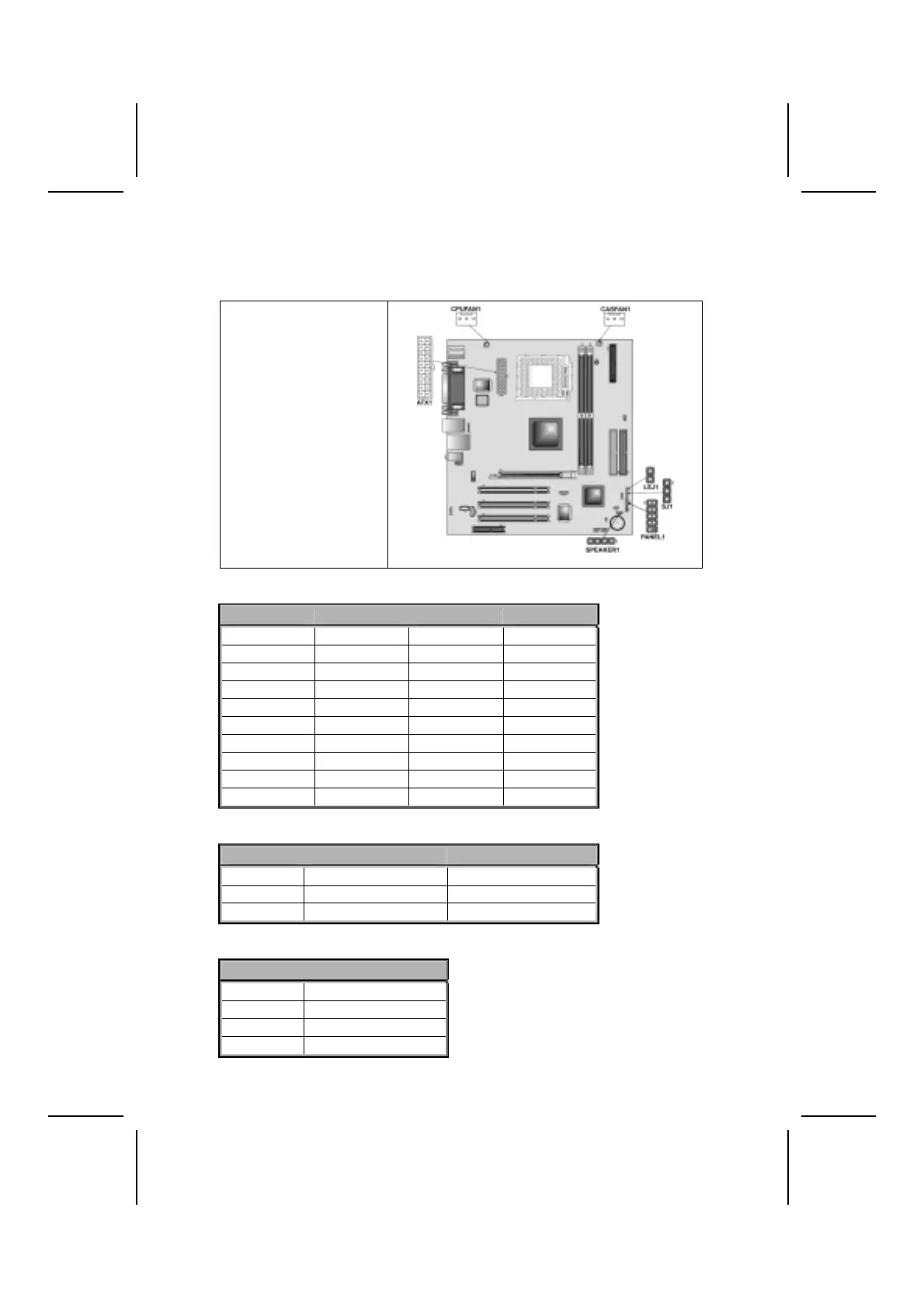
Connecting Case Components
After you have installed the motherboard into a case, you can begin connect-
ing the motherboard components. Refer to the following:
1. Connect the CPU
cooling fan cable to
CPUFAN1.
2. Connect the case
cooling fan connector
to CASFAN1.
3. Connect the case
speaker cable to
SPEAKER1.
4. Connect the case
LED cable to
SJ1/LSJ1.
5. Connect the case
switches and indicator
to PANEL1.
6. Connect the standard
power supply connec-
tor to ATX1.
ATX1: ATX 20-pin Power Connector
Pin Signal Name Pin Signal Name
1 +3.3V 11 +3.3V
2 +3.3V 12 -12V
3 Ground 13 Ground
4 +5V 14 PS ON#
5 Ground 15 Ground
6 +5V 16 Ground
7 Ground 17 Ground
8 PWRGD 18 -5V
9 +5VSB 19 +5V
10 +12V 20 +5V
CPUFAN1/CASFAN1: FAN Power Connectors
Pin Signal Name Function
1 GND System Ground
2 +12V Power +12V
3 Sense Sensor
SPEAKER1: Internal speaker
Pin Signal Name
1 Signal
2 NC
3 NC
4 VCC
10