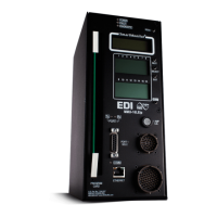
MMU-16LE SmartMonitor
Operations Manual
Eberle Design Inc. Page 8
2.3 VOLTAGE MONITORING
2.3.1 +24VDC SUPPLY MONITORING
The +24V MONITOR I and +24V MONITOR II inputs are provided for monitoring two
+24Vdc supplies in the cabinet assembly. Should loss of proper voltage occur at either of
these inputs, the MMU-16LE SmartMonitor
®
will enter the fault mode, transfer the OUTPUT
relay contacts to the Fault position, and display the appropriate 24V-1 or 24V-2 status
screen. The MMU-16LE SmartMonitor
®
will automatically reset the OUTPUT relay when the
correct input voltages are restored to both of these inputs. The MMU-16LE SmartMonitor
®
will remain in the fault mode for at least the time determined by the Minimum Flash
programming.
A voltage greater than the +24V Monitor input threshold (Section 8.1.4) applied to both of
the +24V MONITOR inputs will be sensed by the MMU-16LE SmartMonitor
®
as adequate
for operation of the cabinet assembly. A voltage less than the +24V Monitor input threshold
applied to either of the +24V MONITOR inputs will be sensed as inadequate for proper
operation. When a +24V MONITOR input is sensed as inadequate for more than the +24V
Monitor Fault time (Section 9), the MMU-16LE SmartMonitor
®
will enter the fault mode and
transfer the OUTPUT relay contacts to the Fault position. When a +24V MONITOR input is
sensed as inadequate for less than the +24V Monitor No-Fault time, the MMU-16LE
SmartMonitor
®
will not transfer the OUTPUT relay contacts to the Fault position. A +24Vdc
failure during the programmed Minimum Flash time or during an MMU Power Failure will
not cause a fault condition.
2.3.1.1 +24VDC MONITOR INHIBIT INPUT
A +24V MONITOR INHIBIT input is provided to inhibit the operation of the +24Vdc Monitor.
Application of a logic TRUE (low) state to this input will disable the operation of the +24Vdc
Monitor.
2.3.1.2 +24VDC MONITOR LATCH INPUT
A jumper position is supplied on the Programming Card to allow +24Vdc failures to latch in
the fault condition until the unit is reset by the activation of the RESET button or the
EXTERNAL RESET input. See Section 6.2.4 for the programming procedure. A +24Vdc
failure during the programmed Minimum Flash time or during an MMU Power Failure will
not cause a latched fault condition.
2.3.1.3 +24VDC MONITOR II 12VDC MODE
The MMU-16LE SmartMonitor
®
offers the capability of setting the threshold for the +24V
MONITOR II input to levels suitable for monitoring a 12 Vdc power supply. This mode is
enabled by the Unit Option called "24V-2 = 12 Vdc" in the SET / VIEW CONFIG menu. See
Section 6.3.4.5.
2.3.2 CONTROLLER VOLTAGE / FAULT MONITOR INPUT
This input is to be connected to the CONTROLLER UNIT VOLTAGE MONITOR (CVM) or
FAULT MONITOR (FM) output from the Controller Unit. When the TRUE (low) state is
absent for more than the CVM Fault time (Section 9), the MMU-16LE SmartMonitor
®
will
enter the fault mode, transfer the OUTPUT relay contacts to the Fault position, and display
the CVM status screen. When the TRUE (low) state is absent for less than the CVM No-
Fault time, the MMU-16LE SmartMonitor
®
will not transfer the OUTPUT relay contacts to
the Fault position. The MMU-16LE SmartMonitor
®
will automatically reset the OUTPUT
relay when the True (low) state is restored to the input. The MMU-16LE SmartMonitor
®
will
remain in the fault mode for at least the time determined by the Minimum Flash
programming. A CVM failure during the programmed Minimum Flash time or during an
MMU Power Failure will not cause a fault condition.

 Loading...