A301-05-880 Issue A
Page 4 © Edwards Limited 2014. All rights reserved.
Edwards and the Edwards logo are trademarks of Edwards Limited.
Introduction
1.2.2 General construction
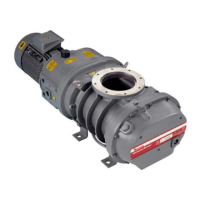
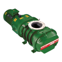
The EH pumps are positive displacement Roots vacuum pumps. The pump mechanism is driven by a three-phase
electric motor through a hydrokinetic drive (see Section 1.2.4).
All of the motors are air cooled.
The pump shafts and rotors are made of cast SG iron. The internal and external shaft seals are made of
polytetrafluoroethylene (PTFE) or fluoroelastomer.
The pump bearings, gears and seals are lubricated by oil fed from reservoirs in the hydrokinetic drive/gearbox. A
series of seals stops the oil from reaching the vacuum side of the EH pump. The hydrokinetic drive/gearbox is
evacuated. Inspect the oil levels through sight glasses that are fitted to the hydrokinetic drive/gearbox. Oil filler, oil
drainage and external evacuation connections are provided on the hydrokinetic drive/gearbox.
The timing gears on all of the EH1200, EH2600 and EH4200 model pumps are lubricated by oil inside the gear cover.
An oil filler connection is provided. The oil level can be inspected through a sight glass fitted to the gear cover.
1.2.3 Principle of operation
The EH pump is shown in Figure 1 and 2. The motor shaft drives one of the rotors through the hydrokinetic drive. The
1:1 gears inside the hydrokinetic drive/gearbox drive the second rotor in the opposite direction inside the stator
housing. A small, accurately gauged clearance is maintained between the rotors and between each rotor and the
stator wall. This clearance allows the EH pump to operate at high speed without mechanical wear and without the
need for lubrication inside the swept volume.
1.2.4 Hydrokinetic drive
The hydrokinetic drive consists of a fluid coupling which connects the electric motor shaft to the rotor. This system
is configured so that when the gas load is high, the rotational speed of the rotors is reduced. As the gas load
decreases, the rotors accelerate to full speed. This allows continuous operation of the EH pump over the vacuum
range without the risk of overloading the motor and removes the need for bypass valves and associated pipelines.
The fluid coupling is viscosity sensitive. The two versions of the EH pump (for hydrocarbon and PFPE oils) have fluid
coupling drives which are specifically designed for the type of oil used in the pump.
1.3 Chemical & ATEX pumps
This manual does not cover these applications. They are covered in publication number A301-51-880.