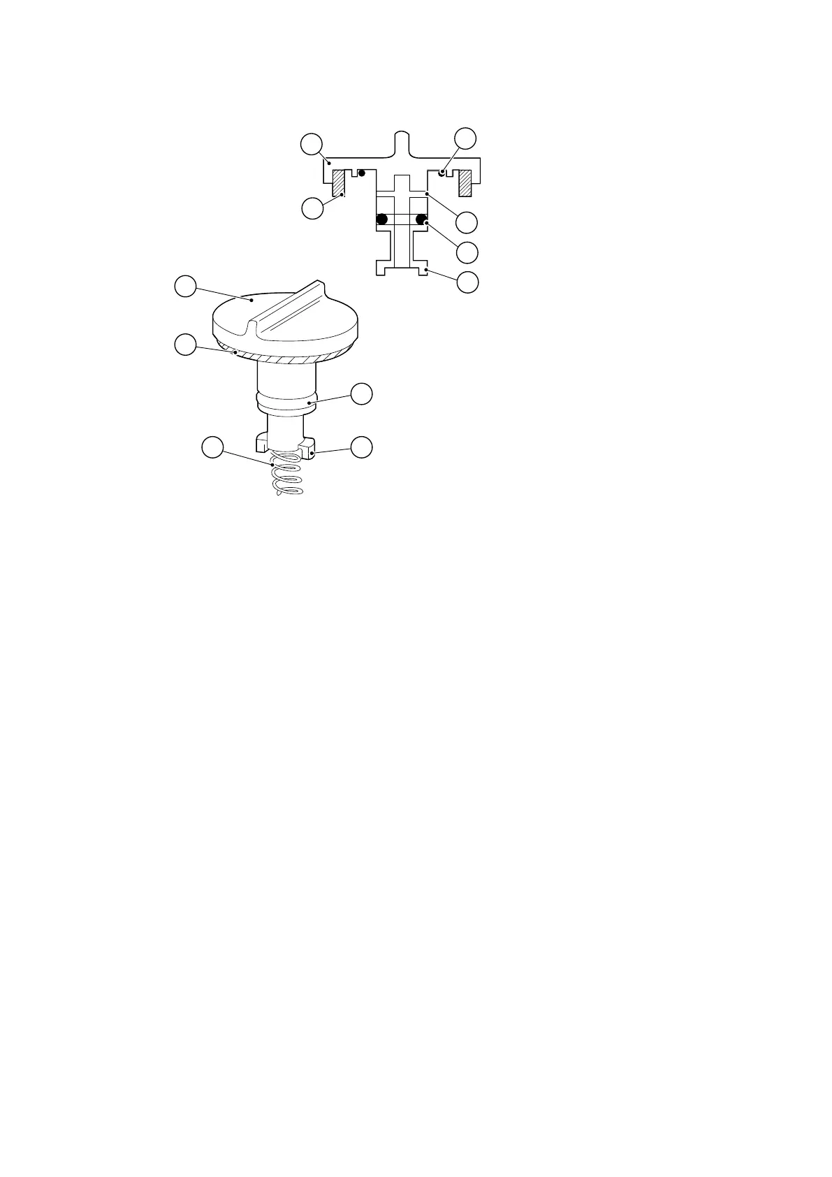
Figure 8 Gas-ballast control assembly
1. Gas-ballast control 2. O-ring
3. Air-hole 4. O-ring
5. Bayonet-lugs 6. Compression spring
7. Filter element
1. Gas-ballast control 2. O-ring
3. Air-hole 4. O-ring
5. Bayonet-lugs 6. Compression spring
7. Filter element
6.7 Clean the oil-level sight-glass
Refer to Figure: Sight-glass assembly for the item numbers in brackets.
1. Drain the oil as described in Replace the oil on page 42.
2. Undo the two screws (1) and remove the bezel (2), the sight-glass (3) and the O-
ring (4) from the oil-box (5).
3.
Clean the screws, bezel and sight-glass with a suitable cleaning soluon.
4. Wipe the O-ring with a clean, dry, lint-free cloth.
5.
Wipe the sight-glass recess in the oil-box with the cloth.
6.
Ret the O-ring, sight-glass and bezel and secure with the two screws.
7.
Rell the pump with oil as described in Replace the oil on page 42.
8.
Check that the sight-glass does not leak.
03/2021 - ©Edwards Limited
Page 44A65201880_AA
A65201880_AA - Maintenance