Connection Reference 1
Connecting Lines 1 & 2 from the circuit board (existing service) to the AutoBooster™:
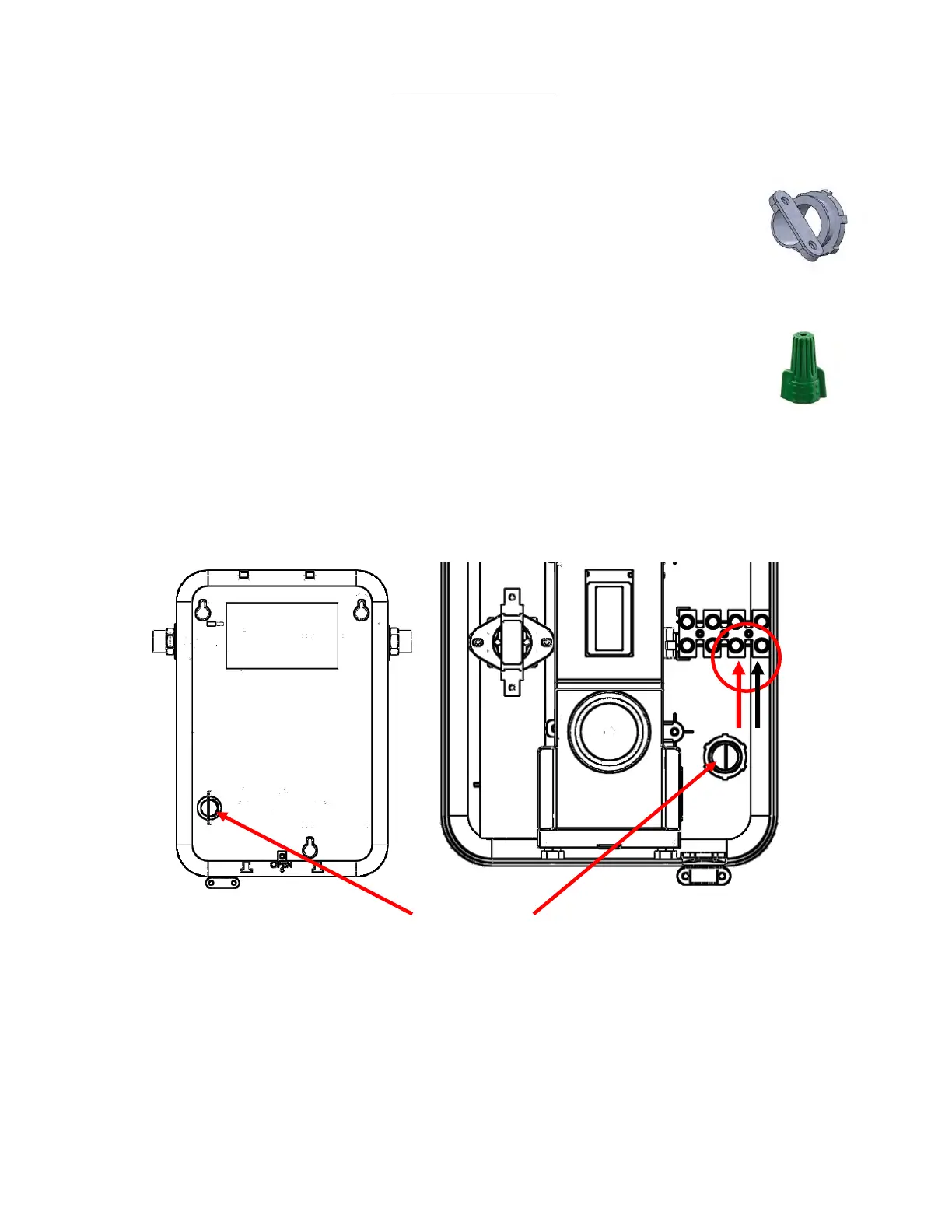
1. Remove the control knob from the unit, then remove the cover of the unit. Two
screws must be removed in order to do this.
2. For this step, if the leads from the breaker are wrapped in a common household
cable jacket, make sure the ends of the leads are exposed from the external
jacket at least 10 inches. Strip back ⅜” to bare copper on L1 and L2.
L1, L2 and ground (from the circuit breaker) will be connected to the
AutoBooster™ inner terminal block. Make sure to thread these lines into the
heater from the backside via the back plate hole, using the supplied cord
grommet.
Connect Line 1 (black) to the “L1” labelled wire terminal, and Line 2 (red) to
the “L2” labelled wire terminal, using a flathead screwdriver to secure the
terminal.
Using a supplied wire nut, connect the circuit breaker ground wire to the green ground wire
stem already inside the unit, which will be exposed. Twist wires together, then twist the wire
nut with both wires inside to secure the connection.
L1/L2 Terminals
Back Plate Hole
(Installer must secure cable clamp here)
3. Tighten the connections on the terminal block with a flathead screwdriver. MAKE SURE WIRES ARE
INSERTED ALL THE WAY IN THE TERMINAL, AND THAT THE SCREWS SECURING THE CONNECTION
ARE TIGHT AND SECURE. FAILURE TO DO THIS WILL CAUSE HEATER MALFUNCTION. Wire
insulation should not be inserted into the terminal block as this will inhibit a good electrical
connection.
4. Proceed to Connection Reference 2 on following page.
Downloaded from https://gadgetsgo.com/AutoBooster-HATB007240-water-tank-heater-boost.html Authorized Eemax Dealer