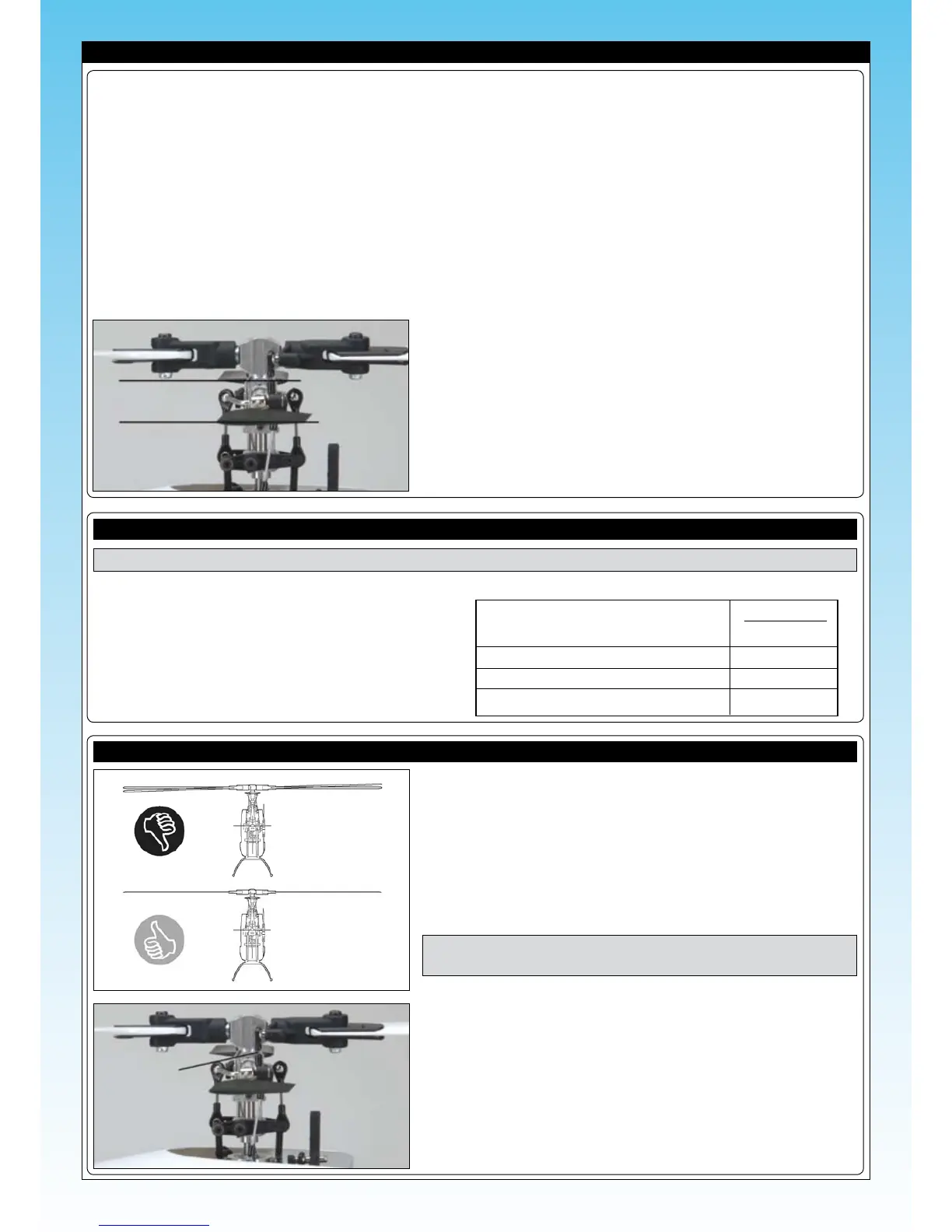
❑ Double-check that the paddles are level when all of the controls are
centred. Both paddles should be even with each other, too.
Before ying your helicopter for the rst time, it's important to double-check everything once more and to make sure that you've set
the helicopter up properly for its rst few ights.
PREFLIGHT SETUP
❑ Double-check that all of the screws used throughout assembly are tight. All screws should be secured in place using thread-lock
(if threaded into metal) or with a small drop of thin C/A if threaded into nylon or composite material. This will prevent the screws
from loosening during ight.
❑ Before each ight you should range-test your radio control system to ensure that it is functioning properly.
❑ Double-check that you've installed the servo horn retaining screws in all of the servos.
❑ Double-check that the main rotor blade screws and the tail rotor blade screws are snug, but not too tight.
❑ Double-check that all of the controls are working properly and that they are moving in the correct direction.
Paddles parallel and
level with each other
ADJUSTING THE PITCH SETTINGS
❑ First, centre all four control sticks and double-check
that the servo horns and the swashplate are centred, as
described previously.
❑ Use a pitch gauge to adjust the collective pitch range
shown right. These gures should be used only as a guide
as the total pitch will be dictated by the battery you are
using.
IMPORTANT Before making adjustments, unplug the motor from the ESC. This will ensure that the motor doesn't turn on.
Pitch Degrees
(Positive) Full Positive Collective +8 ~ +9
Hovering Point +4 ~ +5
Neutral Collective 0
(Negative) Full Negative Collective -8 ~ -9
❑ Mark the tip of one rotor blade with a coloured highlighter pen. This will
aid the identication of a high or low blade.
❑ Smoothly open the throttle until the heli begins to lift off and watch the
rotational plane (tracking) of the rotor blades. The rotational plane of both
rotor blades should be the same. If they are not, adjustments need to be
made to one blade.
IMPORTANT When spinning, both blades should be even with each
other. They should not appear to waver or oscillate up and down.
CHECKING MAIN ROTOR BLADE TRACKING
❑ To adjust the blade, disconnect the ball-end from the lower blade linkage
with the higher rotational plane and tighten the ball-end 1 full turn.
❑ Reconnect the ball-end and test the rotational plane of the rotor blades
again. Repeat the procedure until satised with the alignment.
❑ When completed, you can wipe off the highlighter pen mark.
Adjust links on
either side of the
head to correct
tracking errors