4. Check whether all wires and contacts have been connected correctly.
5. Cover the unused sockets of the DC input with the supplied protective caps.
6. Start up the photovoltaic solar inverter.
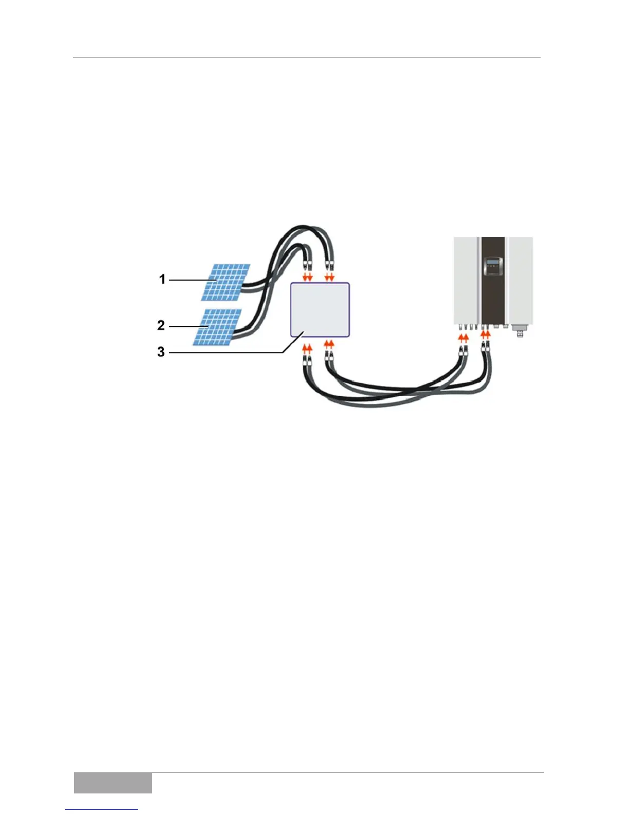
5.2.3 Overview of cabling for the PV module
1 String A
2 String B
3 DC connection socket switched off
Fig. 5.2.3 - 1 ES4200 / ES5000 cabling overview using 4-pin
DC disconnector for each string on tracker A and/or B