55
The troubleshooting process
F
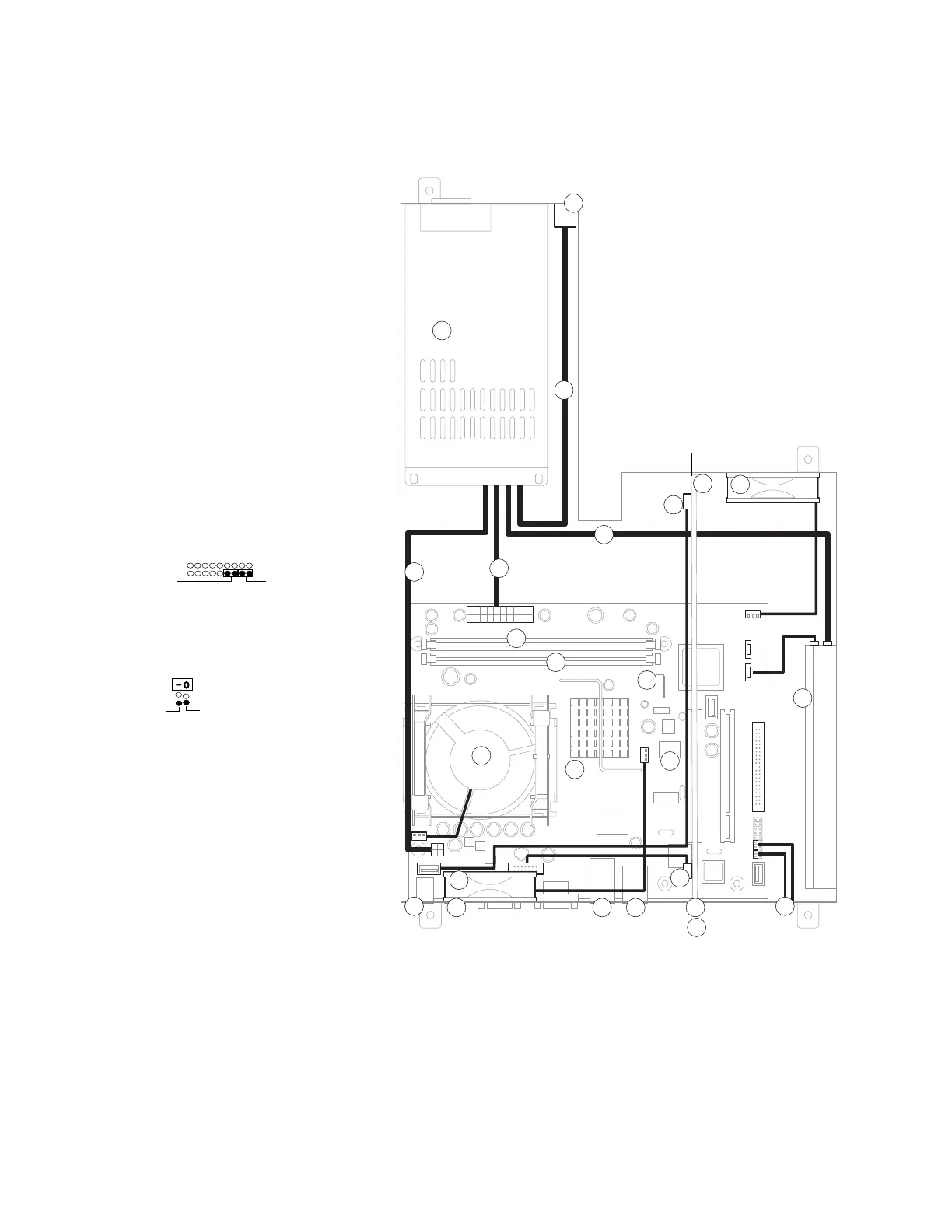
IGURE Z Cable diagram
Key to components, cabling, and
motherboard labels
1. Fiery X3eTY motherboard
2. HDD, cable to SATA1
3. DIMM slots:
a) DIMM2 for standard DIMM
b) DIMM1 for optional DIMM
4. Battery in battery socket F4
5. CPU cooling assembly to FAN1
6. Interface cable connectors to
print engine:
a) interface board connector
b) COPIER port in LAN2
7. LAN port in LAN1
8. USB Type A ports (3) in USB
9. USB Type B port in USBTYPE-B
10. Interface board in PC11:
a) J632 to motherboard JP22
b) J20 to motherboard J29
11. Service switches on interface board
12. Soft power button cables to Front
Panel connector:
13. Bottom fan to FAN3
14. Top fan to FAN2
15. AC power switch:
16. Power supply:
a) to power switch
b) to HDD
c) to J18
d) to J11
17. BIOS chip
NOTE: Connectors that are not
described are not used.
SW SW LED
Front Panel
White
Black
1
2
3a
4
5
7
8
9
10
6a
6b
11
12
HDD
Motherboard
Interface Board
Power supply
Power switch
Bottom fan
Top fan
14
13
15
16
3b
16a
16b
16c
16d
10a
10b
17
 Loading...