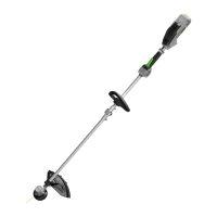
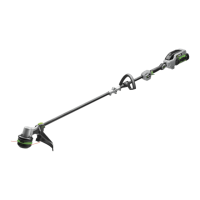
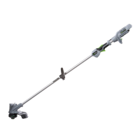
56 VOLT LITHIUM-ION COMMERCIAL CORDLESS LINE TRIMMER — STX450012
DESCRIPTION
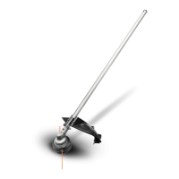
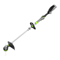
KNOW YOUR LINE TRIMMER (Fig. A)
1. Speed Indicator
2. Bluetooth
®
Indicator
3. Speed Mode Button
4. Battery-status Indicator
5. Rear Handle
6. Carrying Eyelet
7. Loop Handle
8. Shoulder Strap
9. Shaft
10. Trimmer Line
11. Release Tab
12. Trimmer Head (Bump head)
13. Line-cutting Blade
14. Line Trimmer Guard
15. Threshold Ring
16. Lock-off Lever
17. Trigger Switch
18. Battery-release Button
19. Latch
20. Safety Barrier Bar
21*. Outer Flange
22*. Nut
23. Hex Key
24. Sealing Bolt (2)
25*. Brush Cutter Guard
26*. 3-tooth Blade
27*. Blade Sheath
* SOLD SEPARATELY
ASSEMBLY
WARNING: If any parts are damaged or missing, do
not operate this product until the parts are replaced. Use
of this product with damaged or missing parts could result
in serious personal injury.
WARNING: Do not attempt to modify this product or
create accessories not recommended for use with this line
trimmer. Any such alteration or modification is misuse and
could result in a hazardous condition leading to possible
serious personal injury.
WARNING: To prevent accidental starting that could
cause serious personal injury, always remove the battery
pack from the machine when assembling parts.
WARNING: When the machine is equipped with
brush cutter head, the safety barrier bar shall be mounted.
MOUNTING THE GUARD (FIG. B1 & B2)
WARNING: Always wear gloves when mounting or
replacing the guard. Take care of the blade on the guard
and protect your hand from cutting.
WARNING: Never operate the machine without
the guard firmly in place. The guard must always be
on the machine to protect the user! When the guard is
fixed, never attempt to remove or adjust the guard, if
a replacement is needed, it should be performed by a
qualified service technician!
NOTICE: There are two kinds of guards compatible with
this machine. Only the guard with icon can be used
with line trimmer head and must NOT be used with brush
cutter head. Be careful to choose the correct guard when
using the machine.
NOTICE: The brush cutter guard is sold separately.
Loosen and remove the two bolts from the guard, align
the guard mounting holes with the assembly holes and
then lock the guard onto the shaft base with the two bolts,
together with two spring washers.
WARNING: Make sure the guard is fixed according
to Fig. B1 & B2, any reverse fixing will cause great danger!
MOUNTING AND ADJUSTING THE LOOP HANDLE
1. Stop the motor and remove the battery pack from the
machine, if installed.
2. Loosen the wing nut to separate the adjustable loop
handle (Fig. C).
NOTICE: Must install the safety barrier bar onto the loop
handle when the machine is equipped with brush cutter
head.
3. Push the loop handle onto the shaft between the
threshold ring and the warning label (Fig. D1).
4. Insert the clamping block into the handle slot (Fig. D2).
5. Align the recessed part in the barrier bar with the
protruded part on the loop handle, press the barrier
bar onto the loop handle (Fig. D3).
6. Mount the quick-release lever and tighten the wing

 Loading...