'PS&J.PEFMT0OMZ5IFTFBMBSNTVTFTQPXFSFEGPSMJGFMJUIJVNCBUUFSJFTBOEBSF
OPUSFQMBDFBCMF$IFDLUIFA3FQMBDFCZMBCFMPOUIFTJEFXBMMJGJUIBTCFFOFYDFFEFE
SFQMBDFUIFFOUJSFVOJU*GUIFA3FQMBDFCZEBUFIBTOPUCFFOFYDFFEFEUIFOUIF"MBSN
NBZCFGBVMUZBOEOFFETUPCFSFUVSOFEUPUIFNBOVGBDUVSFSo4FFAGetting the CO
Alarm ServicedTFDUJPO
'PS FOWJSPONFOUBMMZ TPVOE EJTQPTBM SFNPWF UIF "MBSN GSPN JUT NPVOUJOH QMBUF
GPS &J NPEFMT PQFO UIF CBUUFSZ EPPS BOE SFNPWF UIF CBUUFSJFT BOE EJTQPTF JO
BDDPSEBODFXJUICFTUQSBDUJDFBOEHVJEBODFPO8&&&EJTQPTBMBOESFDZDMJOH
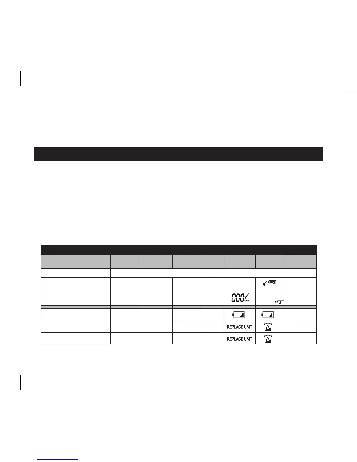
Quick Test with Carbon Monoxide
5IF$BSCPO.POPYJEF"MBSNDIFDLTGPS$0HBTFWFSZ
TFDPOETBOEXIFOFYQPTFEUPUIF$0HBTUIFSFE
MJHIUXJMMGMBTIBTQFS5BCMF#UPDPOGJSNUIBUJUJT
EFUFDUJOHUIF$0HBT
5IF"MBSNDBOCFUFTUFEXJUIDBSCPONPOPYJEFHBT
CZ VTJOH POF PG UIF LJUT UIBUDPNFT XJUI UIF HBT
FJUIFS JO B HMBTT QIJBM PS BFSPTPM DBO 'PMMPX UIF
JOTUSVDUJPOTPOUIFLJU
*G B UFTU HBT LJU JT OPU SFBEJMZ BWBJMBCMF JU JT BMTP
QPTTJCMF UP HBT UFTU UIF "MBSN VTJOH B KPTT TUJDL
PS DJHBSFUUF TNPLF 5P EP UIJT SFNPWF UIF "MBSN
GSPNJUTCBTFBOETMJEFUIFQPXFSTXJUDIUPUIF0/
QPTJUJPO 4FF GJH 'JMM B TVJUBCMF TJ[F QMBTUJD CBH
XJUI TNPLFGSPNUIFKPTTTUJDLPS DJHBSFUUF *OTFSU
OFF
Position
ON
Position
Figure 9