EasyManua.ls Logo

Eiki LC-XB200A - User Manual

Eiki LC-XB200A
118 pages
Print Icon
To Next Page IconTo Next Page
Loading...
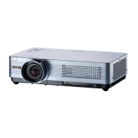
Multimedia Projector
SERVICE MANUAL
PRODUCT CODE
LC-XB100A LC-XB200A
1 122 463 21 (KB5BE) 1 122 473 21 (KG5BE)
1 122 464 21 (LB5BE) 1 122 474 21 (LG5BE)
1 122 464 26 (LB5GE) 1 122 474 26 (LG5GE)
Original Version
Chassis No. KB5-XB100A00
KG5-XB200A00
REFERENCE NO. SM5111169-00
FILE NO.
Model No. LC-XB100A
LC-XB200A
U.S.A, Canada,
Europe, Hong Kong
FOREWORD
For your convenience, all service parts, identified in this manual are available through Eiki’s normal distribution chan-
nels. In addition to service part number, the generic descriptions have been given, where possible, to allow your
service technicians to substitute equivalent components which might be available from other sources.
All orders for service parts will be honored. However, in instances where generic components are considered to be
available from several common sources, as would be the case with an industry standard fuse, resistor, or semicon-
ductor, it may be more economical and expeditious to purchase the part locally.
Give complete Chassis No. for parts
order or servicing, it is shown on the
rating sheet on the cabinet on the projector.

Table of Contents

Questions and Answers

Summary

SERVICE MANUAL

FOREWORD

Introduction to the service manual, parts availability, and ordering.

Safety Instructions

Safety Precautions

Essential safety measures to be followed during projector servicing.

Service Personnel Warning

Warnings for service personnel regarding lamp, UV radiation, and high voltage.

Product Safety Notice

Emphasis on using specific replacement parts for product safety.

Specifications

Mechanical Information

Details on projector type, dimensions, weight, and feet adjustment.

Panel Resolution

Information about LCD panel system, resolution, and pixel count.

Signal Compatibility

Supported color systems and high-definition TV signal formats.

Scanning Frequency

Horizontal and vertical sync frequencies supported by the projector.

Optical Information

Projection image size, throw distance, lens specifications, and lamp details.

Interface

List of video, audio, computer, and network input/output connectors.

Audio

Internal audio amplifier specifications and speaker details.

Power

Voltage requirements and power consumption details.

Operating Environment

Recommended operating and storage temperature ranges.

Remote Control

Specifications for the remote control, including battery and dimensions.

Circuit Protections

Thermal switch

Description of the thermal switch (SW902) and its function.

Lamp cover switch

Explanation of the lamp cover switch (SW901) that cuts off drive signal.

Fuse

Location and specifications of the internal fuse, including part numbers.

Circuit Protections

Warning temperature and power failure protection

How the projector shuts down due to high temperature or power failure.

Maintenance

Cleaning the Air Filter

Step-by-step guide for cleaning projector air filters and precautions.

Resetting the Filter Counter

Procedure to reset the filter counter after cleaning or replacement.

Maintenance

Attaching the Lens Cover

Instructions for attaching the lens cover when the projector is not in use.

Cleaning the Projection Lens

Method for gently cleaning the projector's projection lens.

Cleaning the Projector Cabinet

Guide for cleaning the projector body and cabinet.

Maintenance

Lamp replacement

Detailed procedure for replacing the projector lamp, including safety warnings.

Lamp Replacement

How to check Lamp Used Time

Procedure to check the total lamp used time and its calculation.

Warning Message on the non-standard lamp used

Information about warning messages when using non-standard lamps.

Security Function Notice

Function Description

Details on Key lock, PIN code lock, and Logo PIN code lock functions.

Resetting procedure

Steps to reset security functions like PIN code and key lock.

Standby mode Notice

Restricted Function at the Eco mode

Table showing functions restricted when Eco mode is selected.

Mechanical Disassembly

Cabinet Top, Front, R;C Board removal

Procedure to remove the cabinet top, front, and R/C board.

Mechanical Disassembly

Main Board, AV Panel and Fan removal

Steps to remove the main board, AV panel, and cooling fans.

Mechanical Disassembly

Speaker(SP901), Fan (FN901),Lamp Unit(LP900) and Optical Unit removal

Procedure for removing speaker, fans, lamp unit, and optical unit.

Mechanical Disassembly

Power Board removal

Steps to remove the power board and its shield.

Mechanical Disassembly

Mounting Duct, Fan(FN903, FN904, FN905) and Filter Board removal

Procedure to remove mounting duct, fans, and filter board.

Optical Parts Disassembly

Projection lens disassembly

Procedure to remove the projection lens from the optical unit.

Integrator lens-in disassembly

Steps for disassembling the integrator lens-in assembly.

Optical Parts Disassembly

LCD Panel;Prism Ass’y removal

Procedure for removing the LCD Panel/Prism Assembly.

Optical Parts Disassembly

Panel Type Check

How to identify and check the type of LCD Panel/Prism Ass'y.

Optical Parts Disassembly

Polarized glass-in disassembly

Procedure for disassembling the polarized glass-in unit.

Polarized glass, Pre-polarized glass removal

Steps for removing polarized and pre-polarized glass components.

Optical Parts Disassembly

Optical unit top removal

Procedure to remove the top part of the optical unit.

Condenser lens disassembly

Steps for disassembling the condenser lens.

Optical Parts Disassembly

Relay lens disassembly

Procedure for disassembling the relay lens assembly.

Optical Parts Disassembly

Locations and Directions

Specifies the correct mounting location and direction for optical parts.

Adjustments

Adjustments after Parts Replacement

Table indicating adjustments needed after replacing specific parts.

Optical Adjustments

Contrast adjustment

Procedure for adjusting the contrast of the projector image.

Optical Adjustments

Integrator lens adjustment

Steps to adjust the integrator lens assembly for color uniformity.

Optical Adjustments

Relay lens-Out adjustment

Procedure to adjust the relay lens for color uniformity.

Electrical Adjustments

Service Adjustment Menu Operation

How to enter and navigate the service mode for adjustments.

Memory IC (IC1371) Replacement

Information on replacing the memory IC and subsequent re-adjustments.

Electrical Adjustments

Circuit Adjustments

Cautionary notes and conditions for adjusting various circuits.

Electrical Adjustments

Output Voltage adjustment

Procedure for adjusting the output voltage after power board replacement.

Fan Control adjustment

Adjusting fan control settings using service mode test points.

Reference Voltage Adjustment

Procedure to adjust reference voltage for projector operation.

Panel Type Check and Setting

Checking and setting the LCD panel type for correct gamma characteristics.

Electrical Adjustments

Auto calibration adjustment [PC]

Steps for PC auto-calibration and adjustments if it fails.

Pedestal adjustment [PC]

Adjusting pedestal level and black level for PC input.

Pedestal adjustment [Component]

Adjusting pedestal and black level for Component input.

Gain adjustment [PC]

Adjusting amplitude for PC input signals (RGB).

Auto Calibration adjustment [Component]

Steps for component auto-calibration and fallback adjustments.

Gain adjustment [Component]

Adjusting amplitude for component input signals.

Electrical Adjustments

Auto Calibration adjustment [Video]

Procedure for video auto-calibration and fallback adjustments.

Gain adjustment [Video]

Adjusting amplitude for video input signals.

Common Center adjustment

Adjusting common center for 50%-Whole Gray computer signal.

50% White adjustment [PC]

Adjusting 50% white level for PC input signals.

White Balance adjustment [PC]

Adjusting white balance for PC input signals.

Electrical Adjustments

White Balance adjustment [Video]

Adjusting white balance for video input signals.

Keystone Offset adjustment

Readjusting Keystone Offset after G-sensor or Memory IC replacement.

Color Shading Correction adjustment

Using software for color shading correction with whole-gray patterns.

Electrical Adjustments

Test Points and Locations

Diagram showing test points and their locations on the main board.

Electrical Adjustments

Service Adjustment Data Table

Table of initial values, ranges, and notes for service adjustments.

Electrical Adjustments

Service Adjustment Data Table

Table of initial values, ranges, and notes for service adjustments.

Electrical Adjustments

Service Adjustment Data Table

Table of initial values, ranges, and notes for service adjustments.

Electrical Adjustments

Service Adjustment Data Table

Table of initial values, ranges, and notes for service adjustments.

Electrical Adjustments

Service Adjustment Data Table

Table of initial values, ranges, and notes for service adjustments.

Electrical Adjustments

Service Adjustment Data Table

Table of initial values, ranges, and notes for service adjustments.

Electrical Adjustments

Service Adjustment Data Table

Table of initial values, ranges, and notes for service adjustments.

Electrical Adjustments

Service Adjustment Data Table

Table of initial values, ranges, and notes for service adjustments.

Electrical Adjustments

Service Adjustment Data Table

Table of initial values, ranges, and notes for service adjustments.

Electrical Adjustments

Service Adjustment Data Table

Table of initial values, ranges, and notes for service adjustments.

Electrical Adjustments

Service Adjustment Data Table

Table of initial values, ranges, and notes for service adjustments.

Electrical Adjustments

Service Adjustment Data Table

Table of initial values, ranges, and notes for service adjustments.

Electrical Adjustments

Service Adjustment Data Table

Table of initial values, ranges, and notes for service adjustments.

Electrical Adjustments

Service Adjustment Data Table

Table of initial values, ranges, and notes for service adjustments.

Electrical Adjustments

Service Adjustment Data Table

Table of initial values, ranges, and notes for service adjustments.

Electrical Adjustments

Service Adjustment Data Table

Table of initial values, ranges, and notes for service adjustments.

Electrical Adjustments

Service Adjustment Data Table

Table of initial values, ranges, and notes for service adjustments.

Chassis Block Diagrams

Chassis over view

Block diagram illustrating the overall chassis layout and major components.

Chassis Block Diagrams

System control

Block diagram of the system control circuit and its connections.

Chassis Block Diagrams

Lamp control

Block diagram detailing the lamp control circuit.

Chassis Block Diagrams

Audio circuit

Block diagram of the audio circuit, showing signal flow and components.

Chassis Block Diagrams

Power supply & protection circuit

Block diagram of the power supply and protection circuits.

Chassis Block Diagrams

Fan control circuit

Block diagram illustrating the fan control circuit and its logic.

Chassis Block Diagrams

IIC bus Control circuit

Block diagram of the IIC bus control circuit.

Troubleshooting

Indicators and Projector Condition

Table correlating indicator lights with projector operating conditions.

Troubleshooting

No Power

Troubleshooting steps for situations where the projector does not power on.

Lamp Cover switch

Check the lamp cover mounting and switch (SW901) for no-light issues.

Troubleshooting

No Picture

Troubleshooting guide for scenarios where no picture is displayed.

Troubleshooting

No Sound

Troubleshooting steps for situations where there is no audio output.

Control Port Functions

Scaler I;O Port Functions (PW190)

Description of scaler I/O ports and their functions.

IC Block Diagrams

FA5550 NG <P.F. Control, IC621>

Block diagram of the FA5550NG IC for Power Factor Control.

XR16 L5701 IL24 <UART, IC9885>

Block diagram of the XR16L5701IL24 IC for UART communication.

IC Block Diagrams

MAX232 ECPWRP <RS-232 C Driver, IC3801>

Block diagram of the MAX232ECPWRP IC for RS-232C driver.

L3 E06170 <D;A, S;H-LCD Driver, IC501, IC531, IC561>

Block diagram for L3E06170 ICs used for D/A and S/H-LCD drivers.

IC Block Diagrams

L3 E07111 <LCD Driver & Gamma Correction, IC401>

Block diagram of the L3E07111 IC for LCD driver and gamma correction.

PIC16 F688 T <LAMP ID, IC8741>

Block diagram of the PIC16F688T IC for Lamp ID.

IC Block Diagrams

NJW1156 <Audio Control, IC5001>

Block diagram of the NJW1156 IC for audio control.

PW190 <Scaler, IC301>

Block diagram of the PW190 IC, which functions as a scaler.

IC Block Diagrams

MR4010 <Power OSC, IC631>

Block diagram of the MR4010 IC for Power Oscillator.

PIC18 F67 J60<LAN CONTROL,IC8801>

Block diagram of the PIC18F67J60 IC for LAN control.

IC Block Diagrams

FA7703 <DC-DC Converter, IC7811>

Block diagram of the FA7703 IC for DC-DC conversion.

Sil9127 <HDMI Receiver, IC8001>

Block diagram of the Sil9127 IC functioning as an HDMI receiver.

Electrical Parts List

Read Description in the parts list

Explanation of symbols for capacitor, resistor, and coil specifications.

Electrical Parts List

Electrical Parts Location

Diagrams showing the location of assembled boards and out-of-circuit components.

Electrical Parts List

Electrical Parts List

List of assembled boards, out-of-circuit components, transistors, and integrated circuits.

Electrical Parts List

Electrical Parts List

List of resistors, variable resistors, transformers, coils, diodes, and miscellaneous parts.

Electrical Parts List

Electrical Parts List

List of transistors and integrated circuits with part numbers and descriptions.

Electrical Parts List

Electrical Parts List

List of capacitors with part numbers, descriptions, and voltage ratings.

Electrical Parts List

Electrical Parts List

List of capacitors with detailed specifications, including voltage and tolerance.

Electrical Parts List

Electrical Parts List

List of capacitors with detailed specifications, including voltage and tolerance.

Electrical Parts List

Electrical Parts List

List of capacitors with detailed specifications, including voltage and tolerance.

Electrical Parts List

Electrical Parts List

List of capacitors with detailed specifications, including voltage and tolerance.

Electrical Parts List

Electrical Parts List

List of capacitors with detailed specifications, including voltage and tolerance.

Electrical Parts List

Electrical Parts List

List of capacitors with detailed specifications, including voltage and tolerance.

Electrical Parts List

Electrical Parts List

List of capacitors with detailed specifications, including voltage and tolerance.

Electrical Parts List

Electrical Parts List

List of resistors with material, tolerance, and wattage ratings.

Electrical Parts List

Electrical Parts List

List of resistors with material, tolerance, and wattage ratings.

Electrical Parts List

Electrical Parts List

List of resistors with material, tolerance, and wattage ratings.

Electrical Parts List

Electrical Parts List

List of resistors with material, tolerance, and wattage ratings.

Electrical Parts List

Electrical Parts List

List of resistors with material, tolerance, and wattage ratings.

Electrical Parts List

Electrical Parts List

List of resistors with material, tolerance, and wattage ratings.

Electrical Parts List

Electrical Parts List

List of coils with material, inductance, and frequency specifications.

Electrical Parts List

Electrical Parts List

List of diodes and Zener diodes with part numbers and descriptions.

Electrical Parts List

Electrical Parts List

List of miscellaneous parts, capacitors, resistors, and coils.

Electrical Parts List

Electrical Parts List

List of packing materials, accessories, AC cords, and remote controls.

Mechanical Parts List

Cabinet Parts Location

Diagram showing the location of cabinet parts on the projector.

Mechanical Parts List

Optical Parts Location

Diagrams illustrating the location of integrator and relay lens components.

Mechanical Parts List

Polarized Glass-In

Diagram showing the location of polarized glass-in components.

Condenser (Out) Lens

Diagram showing the location of the condenser lens.

Mechanical Parts List

Projection Lens

Diagram showing the location of the projection lens.

Mechanical Parts List

Prism;LCD Panel Assy

Diagram showing the location of the prism and LCD panel assembly.

Mechanical Parts List

In the Optical Unit

Detailed diagram of parts within the optical unit.

Mechanical Parts List

CABINET PARTS

List of all cabinet parts with their respective part numbers and descriptions.

CHASSIS PARTS

List of all chassis parts with their respective part numbers and descriptions.

SCREWS

List of screws used in the projector assembly with their specifications.

OPTICAL PARTS

List of optical parts with their respective part numbers and descriptions.

Diagrams & Drawings

Schematic Diagrams Printed Wiring Board Drawings

Reference to schematic diagrams and printed wiring board drawings.

Parts description and reading in schematic diagram

Resistor Reading

Explanation of how to read resistor specifications and their codes.

Capacitor Reading

Explanation of how to read capacitor specifications and their codes.

Material table

Table listing materials used for electronic components.

Tolerance table

Table detailing tolerance symbols and their corresponding values.

Diode;Transistor Type Reading

Information on reading diode and transistor types and their markings.

Coil Reading

Explanation of how to read coil specifications, including inductance and codes.

Pin description of diode, transistor and IC

Diode

Illustrations of diode pin configurations.

Transistor;FET

Illustrations of transistor and FET pin configurations.

IC

Illustrations of integrated circuit pin configurations.

FET

Illustrations of FET pin configurations.

Note on Soldering

Solder

Recommendations for using lead-free solder and its composition.

Schematic Diagrams

CAUTION

Safety precautions for servicing projectors with internal converter transformers.

Printed Wiring Board Diagrams

R;C ( SIDE:A)

Printed wiring diagram for the R/C board, side A.

R;C ( SIDE:B)

Printed wiring diagram for the R/C board, side B.

POWER (SIDE:A)

Printed wiring diagram for the power board, side A.

POWER (SIDE:B)

Printed wiring diagram for the power board, side B.

Printed Wiring Board Diagrams

MAIN (SIDE:A)

Printed wiring diagram for the main board, side A.

Printed Wiring Board Diagrams

MAIN (SIDE:B)

Printed wiring diagram for the main board, side B.

Printed Wiring Board Diagrams

LINE FILTER (SIDE:A)

Printed wiring diagram for the line filter, side A.

LINE FILTER (SIDE:B)

Printed wiring diagram for the line filter, side B.

AV (SIDE:A)

Printed wiring diagram for the AV board, side A.

AV (SIDE:B)

Printed wiring diagram for the AV board, side B.

ID CONNECT (SIDE:A)

Printed wiring diagram for the ID connect board, side A.

ID CONNECT (SIDE:B)

Printed wiring diagram for the ID connect board, side B.

Eiki LC-XB200A Specifications

General IconGeneral
BrandEiki
ModelLC-XB200A
CategoryProjector
LanguageEnglish

Related product manuals