MCE2035: User manual
Version: 2011-05-17, rev.: 0a Page: 16
8.2 Connection of power and load cells
This chapter describes the connection of power supply and load cells to the MCE2035
module.
IMPORTANT: The used power supply must be stable and free of transients. It may there-
fore be necessary to use a separate power supply dedicated to the weighing system, and not
connected to any other equipment.
The 10 pole connector (J2) on the MCE2035 module is connected to the 10 pole connec-
tors on the load cell interface modules (MCE2010) and to the 10 pole connector on the
MCE9601 connection module using the supplied ribbon cable with mounted connectors.
Through this bus cable connection of power supply to the individual modules is achieved
and data can be transferred from the load cell modules to the MCE2035 module.
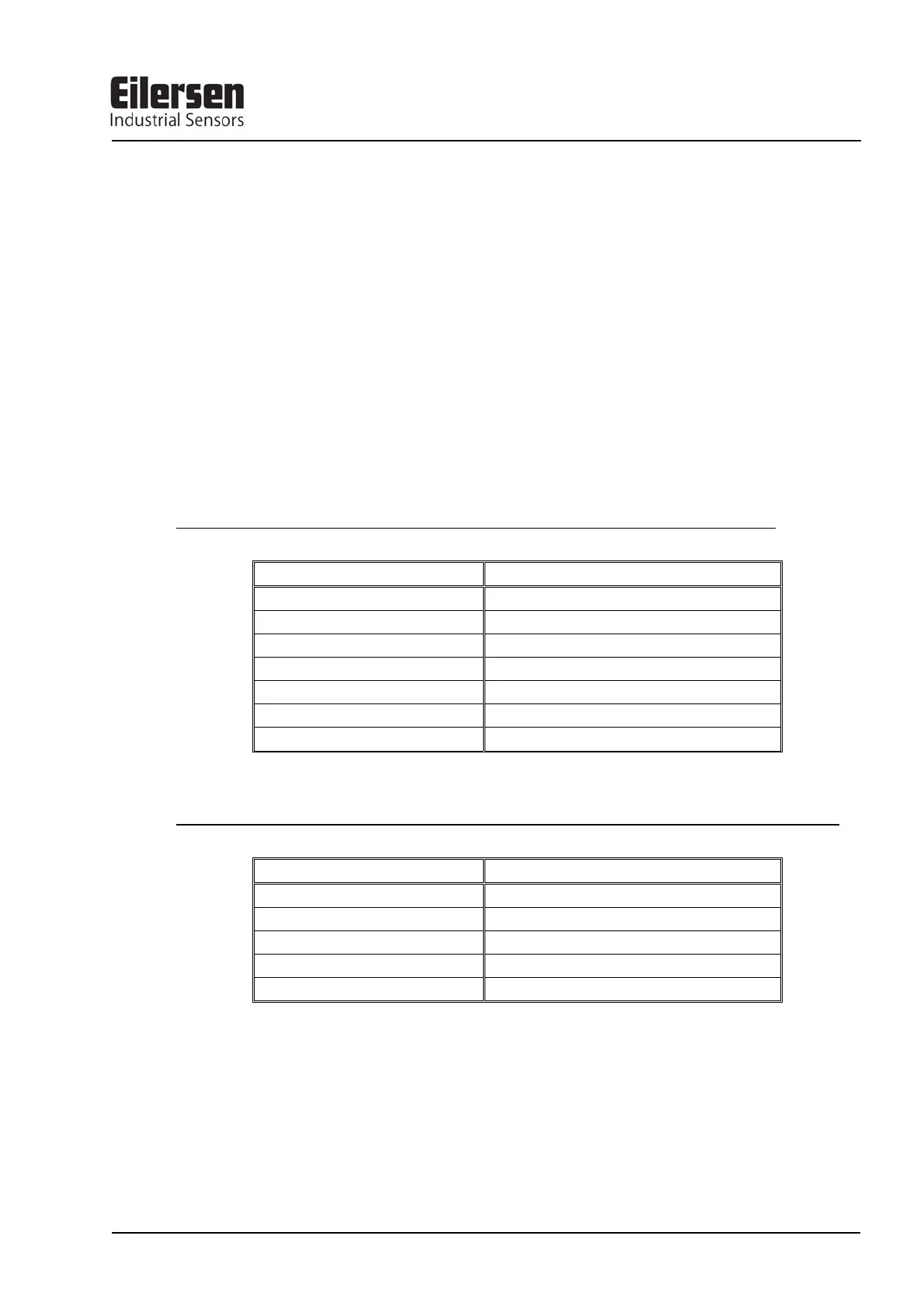
The MCE9601 module has the following connections in the blue connector (J1):
MCE9601 CONNECTOR CONNECTION
GND -
B (DATA- ) -
A (DATA+) -
GND -
+24V +24VDC (Vin)
GND 0 VDC (GNDin)
I/O -
The 10 pole connector (J2) on the MCE2035 Profibus-DP module has these connections:
MCE2035 J2 CONNECTER FUNCTION
J2.1 - J2.2 RS485-B (DATA- )
J2.3 - J2.4 RS485-A (DATA+)
J2.5 - J2.6 0 VDC (GNDin)
J2.7 - J2.8 +24VDC (Vin)
J2.9 - J2.10 I/O line