MCE2035: User manual
Version: 2011-05-17, rev.: 0a Page: 6
4) MCE9601 DESCRIPTION
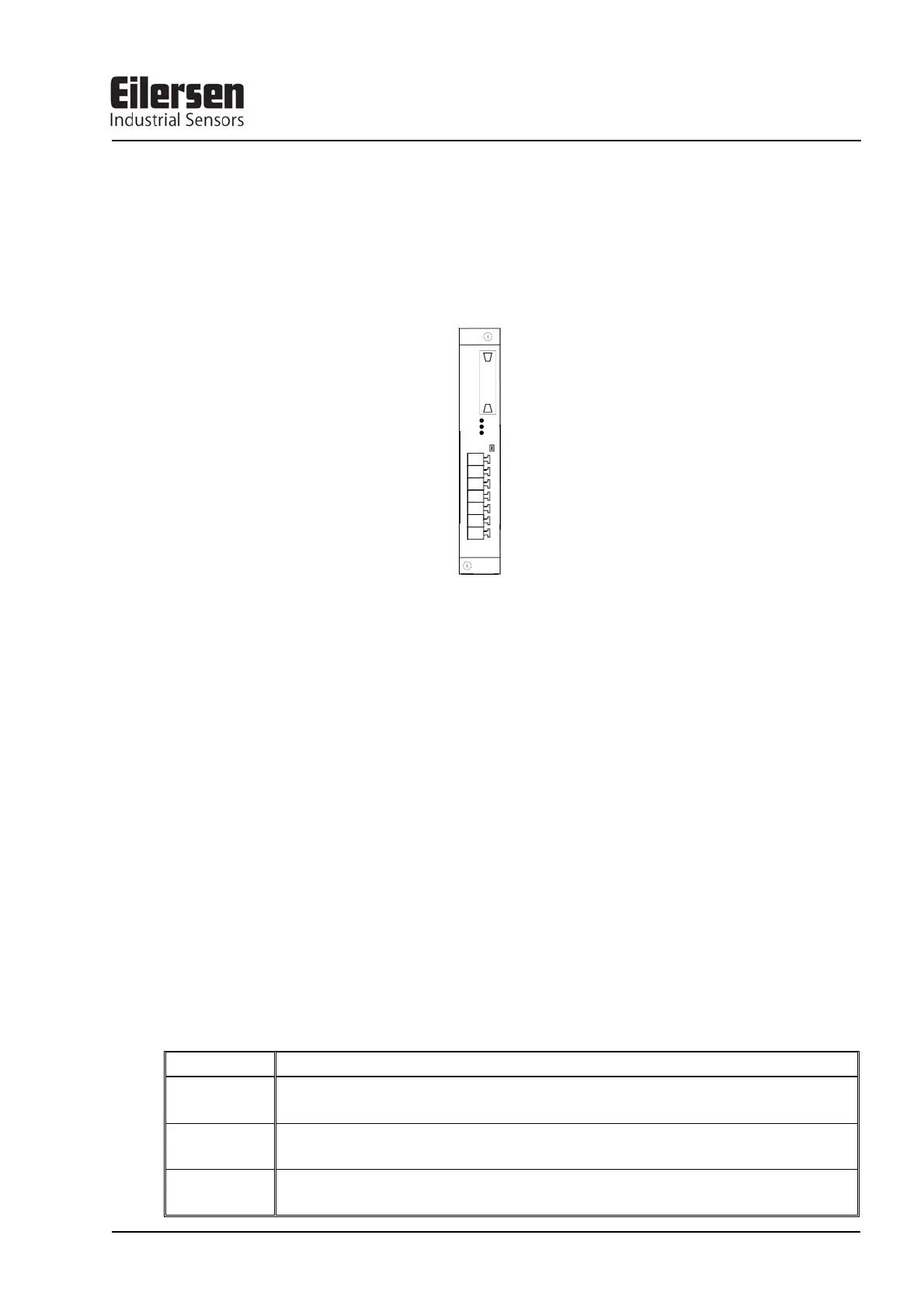
Below the layout of the MCE9601 terminal module is shown. The MCE9601 module is
used for connection between the Eilersen Electric digital load cell bus at one side and
power supply/equipment at the other side.
The J1 terminal block is used for connection of the following:
• Terminals Gnd and B (-) and A (+) gives access to the RS485 bus of all equipment
connected to the load cell bus.
• Terminals Gnd and +24Vdc provides external power to the equipment connected to the
load cell bus. These terminals have to be connected to an external +24VDC power sup-
ply.
• Terminals Gnd and I/O are the internal synchronization signal used by the load cell
modules. Normally these terminals have no external connection and must be left open.
The J2 connector is used for connecting equipment (load cell modules, communication
modules etc.) on the digital load cell bus by using the supplied ribbon cable with mounted
connectors.
The JU1 jumper is used for hardware synchronisation. Normally this jumper should be left
in the default factory setting which is ON.
The light emitting diodes on the MCE9601 module have the following function:
LED Function
D1
(Green)
RS485 Communication. This LED should be ON during normal operation (Actually it is
flashing quickly, but this can look like a steady light).
D2
(Yellow)
This LED should be OFF during normal operation. If this lamp is lit, the I/O pin is at re-
versed polarity.
D3
(Red)
Hardware Synchronisation. This LED should be ON during normal operation (Actually
it is flashing quickly, but this can look like a steady light).
Gnd
B
A
Gnd
+24Vdc
Gnd
I/O
D3
D2
D1
JU1
J
2
J
1