MCE2035: User manual
Version: 2011-05-17, rev.: 0a Page: 5
All switches (SW1) in the load cell module must be at the correct position before use.
Please notice that the switches (SW1) are only read once during power-up. If a change in
the switch setting is necessary the power has to be disconnected and then reconnected (af-
ter 10 seconds). Then the MCE2010 load cell module recognizes the new switch setting.
The switches SW1.1 to SW1.4 are used to select different modes of operation. The below
table is valid for the normal standard software in the load cell module. Unless expressly
specified, the default settings must normally be used.
MCE2010 SW1.1 to SW1.4
SW1 No Default setting Function
1
OFF Baud rate
OFF: 115200
ON: 230400
2
ON Filter, MSB
3
ON Filter, LSB
4
OFF Not used
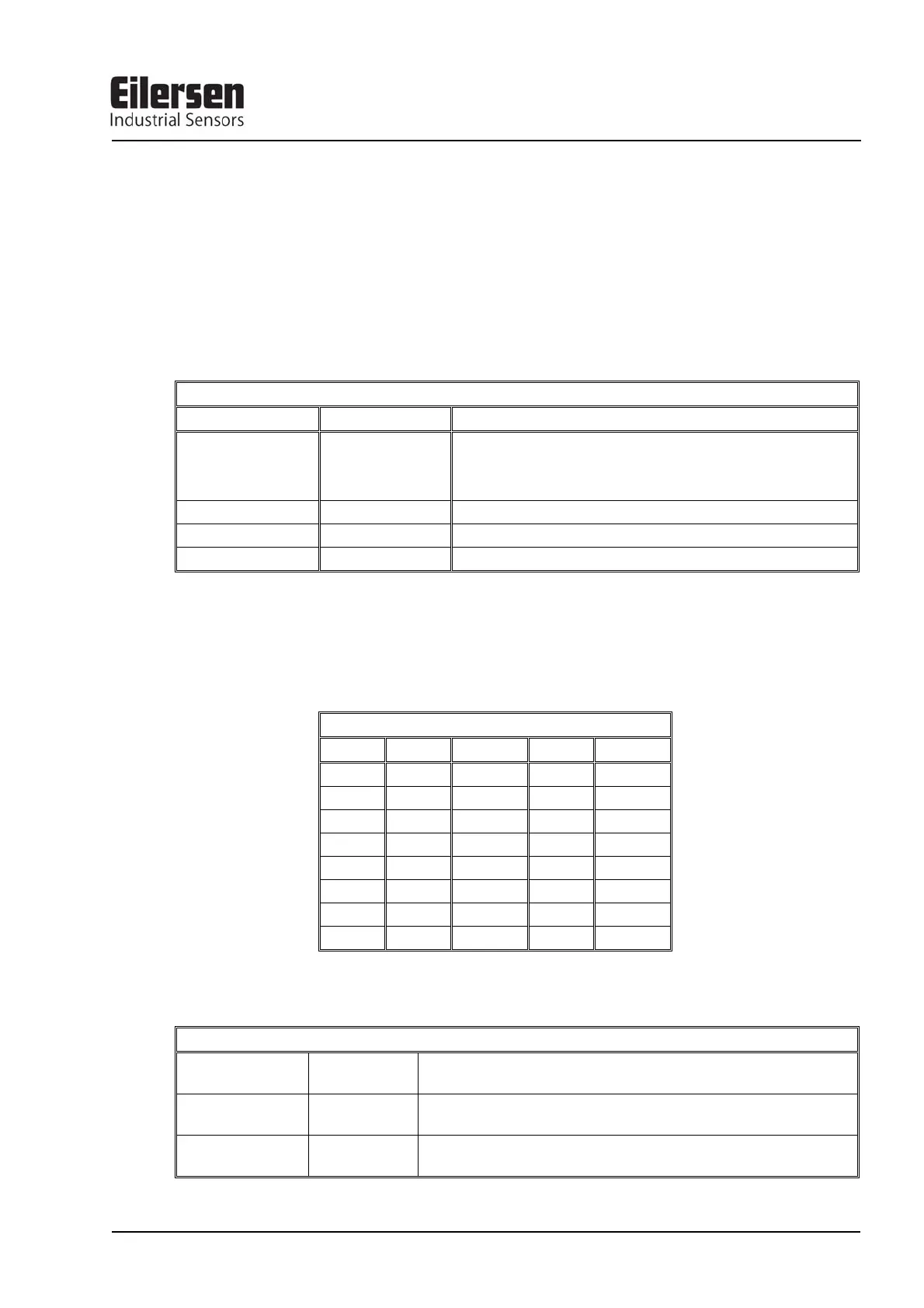
Switch SW1.5 to SW1.8 are used for address selection. All load cell modules must have
unique addresses ascending from 0 with no gaps unless expressly specified otherwise. No
addresses may be skipped and no addresses may be used by more than one load cell mod-
ule. In systems with 1-8 load cells switch SW1.5 must be set to OFF.
MCE2010 SW1.6 to SW1.8
SW1.5 SW1.6 SW 1.7 SW1.8 Address
OFF OFF OFF OFF 0
OFF OFF OFF ON 1
OFF OFF ON OFF 2
OFF OFF ON ON 3
OFF ON OFF OFF 4
OFF ON OFF ON 5
OFF ON ON OFF 6
OFF ON ON ON 7
The three LED’s are used to indicate the following conditions:
MCE2010 LED’S
TXBB
Green Lit whenever the load cell module transmits data. Must be
on/flashing rapidly whenever the system is started.
D1
Yellow No synchronisation between load cell modules: One or more load
cells not connected to load cell module or poor connection.
SYNC ERR
Red No load cell synchronisation: No load cell connected to load cell
module or poor connection.