MCE2035: User manual
Version: 2011-05-17, rev.: 0a Page: 17
8.3 DIP-switch settings
The Profibus-DP module is equipped with a 4 pole DIP-switch block that has the following
function:
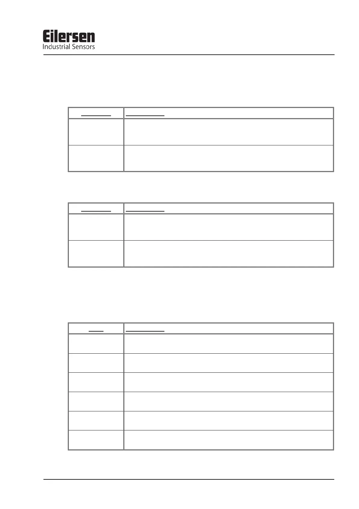
SWITCH FUNCTION
Sw1.1-Sw1.2
Measurement time
Used to select the desired measurement time as described in an earlier chapter. Note
that these switches are only read during power on.
Sw1.3-Sw1.4
Filtering
Used to select the desired filter as described in an earlier chapter. Note that these
switches are only read during power on.
and a 8 pole DIP-switch block that has the following function:
SWITCH FUNCTION
Sw2.1
Scaling
Used to select the desired scaling as described in an earlier chapter. Note that these
switches are only read during power on.
Sw2.2-Sw2.8
Selection of Profibus-DP communication address
The address is selected as the DIP-switches are binary coded, so Sw2.2 is MSB and
Sw2.8 is LSB. Note that these switches are only read during power on.
8.4 Light Emitting Diodes
The Profibus-DP module is equipped with 6 light emitting diodes (LED). These LED’s
have the following function:
LED FUNCTION
TXBB
(Green)
Communication with load cells
Profibus-DP module is communicating with load cells.
D1
(Green)
Reserved for future use
D2
(Green)
Reserved for future use
PBE
(Red)
Profibus Error (when initializing the SPC3)
The SPC3 Profibus-DP controller was not initialized correctly.
DES
(Yellow)
Data Exchange State
Exchange of data between Profibus-DP slave and master.
RTS
(Yellow)
RtS signal (SPC3)
The Profibus-DP module sends to the master.