MCE2035: User manual
Version: 2011-05-17, rev.: 0a Page: 19
8.6 Profibus-DP connector
The Profibus-DP module is equipped with a nine pole female sub-D connector (J1) for
connection to the Profibus-DP network. The connector is a standard Profibus-DP connec-
tor. Termination of the Profibus should take place in the sub-D connector (male) of the ca-
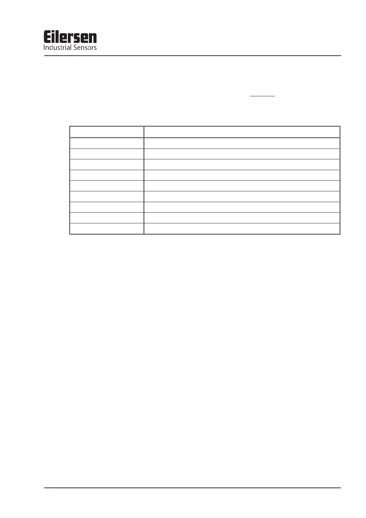
ble. The specific terminals in the connector have the following function:
J1 TERMINALS FUNCTION
J1.1 Not used
J1.2 Not used
J1.3 RS485-A (positive line) (Siemens designation: B line)
J1.4 Request to Send (RTS)
J1.5 0 VDC (Gnd)
J1.6 +5VDC (Vout)
J1.7 Not used
J1.8 RS485-B (negative line) (Siemens designation: A line)
J1.9 Not used
Note that some companies use different designations for the RS485-A and the RS485-B lines. Therefore the
polarity of the lines has been listed.
8.7 Hardware Selftest
During power-on the Profibus-DP module will perform a hardware selftest. The test will
cause the light emitting diodes D1, D2 and PBE to turn on and off shortly, one at a time.
8.8 Update times
Please note that update times across the Profibus-DP communication depends on the specific
Profibus-DP configuration (selected baudrate, number of slaves, scan times etc.).