1
2
3
4
5
6
11.
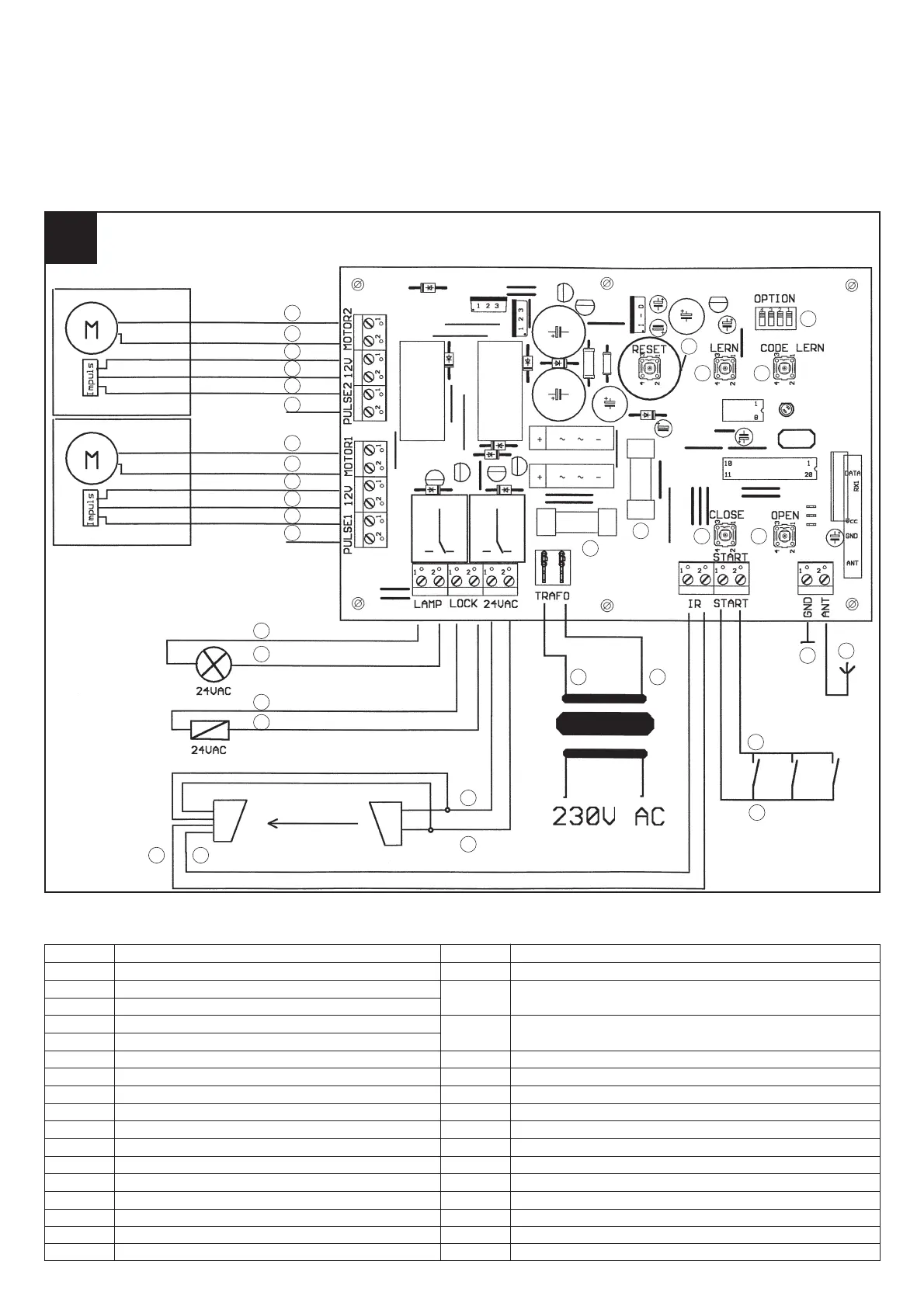
11. Anschlußplan
11. Terminal diagram
11. Schéma des connexions
11. Aansluitschema
11. Diagrama de conexiones
11. Esquema de ligações
11. Anslutningsschema
11. Liitäntäkaavio
11. Koplingsskjema
11. Schema di collegamento
11. Schemat montażowy
11. Csatlakoztatási tervrajz
8
7
9
10
11
12
13
14
15
16
25
22
27
28
31
33
34
3029
32
21
23
24
26
41
17 18
19
20
19 24 V AC für Lichtschranke
20 24 V AC für Lichtschranke
21 Schaltkontakt für Schlüsseltaster,
Innentaster oder Codierschloß
22 Schaltkontakt für Schlüsseltaster,
Innentaster oder Codierschloß
23 Masse für externe Antenne
24 Antennenanschluß
25 Anschluß 1 vom Sicherheitstrafo 24 V AC
26 Anschluß 2 vom Sicherheitstrafo 24 V AC
27 Feinsicherung T 6 A
28 Feinsicherung T6 A
29 Lerntaster für Endposition
30 Lerntaster für Handsender
31 Taster für Tor „ZU“
32 Taster für Tor „AUF“
33 Resettaster
34 Funktionsschalter
1 Motorleitung Motor 2 (grün)
2 Motorleitung Motor 2 (rot)
3 + 12V für Impulsgeber Motor 2 (braun)
4 – 12V für Impulsgeber Motor 2 (grau)
5 Impulsgeber Motor 2 (weiß)
6 GND nicht belegt
7 Motorleitung Motor 1 (grün)
8 Motorleitung Motor 1 (rot)
9 + 12V für Impulsgeber Motor 1 (braun)
10 – 12V für Impulsgeber Motor 1 (grau)
11 Impulsgeber Motor 1 (weiß)
12 GND nicht belegt
13 Anschluß 1 für Blinklicht
14 Anschluß 2 für Blinklicht
15 Anschluß 1 für Elektroschloß
16 Anschluß 2 für Elektroschloß
17 Schaltkontakt Lichtschranke NO
18 Schaltkontakt Lichtschranke NO