Do you have a question about the EK-Quantum Reflection2 PC-O11D XL D5 PWM D-RGB and is the answer not in the manual?
| Compatibility | Lian Li PC-O11D XL |
|---|---|
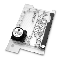
| Pump Type | D5 PWM |
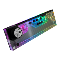
| Lighting | D-RGB |
| D-RGB cable length | 500 mm |
| Rated voltage | 12V DC |
| Power consumption | 23W |
| Maximum pressure head | 3.9 m |
| Maximum flow rate | 1500 L/h |
| Maximum system temperature | 60°C |
| Power connector | 4-pin Molex |
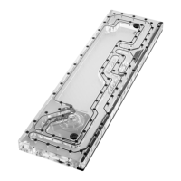
| Material | Acrylic |
| Reservoir Volume | 300 ml |
| D-RGB connector | 3-pin 5V digital LED header |
| Pump electrical and mechanical properties | PWM controlled |
| Pump Materials | PPS-GF40, EPDM O-rings |
| Weight | 2.1 kg |
| Ports | G1/4" |
Unscrew factory screws and remove the top panel from the case.
Remove both side panels and the front panel from the case.
The SSD Trays need to be removed from the back side of the chassis.
Unscrew the 2 marked factory screws and remove the bottom Radiator bracket.
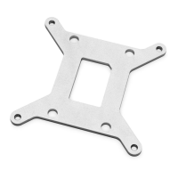
Remove plastic tabs from original bracket and reattach to replacement.
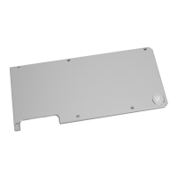
Unscrew M3 screws and remove the metal plate from the distribution plate.
Carefully place the distribution plate into the PC case and align mounting holes.
Secure the distribution plate to the chassis using M4 screws and M4 nuts.
Reattach the stored metal plate using M3 screws after securing the distribution plate.
All ports must be used as marked; close unused ports with supplied plugs.
If components are not installed, join one INLET and one OUTLET port.
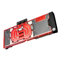
Use only one INLET/OUTLET for GPU; close others with G1/4 plugs.