EKO INSTRUMENTS CO., LTD. - Pyranometer MS-80/80S/80U - Instruction Manual Ver. 1
Pg. 58
・ The byte order for communication is big endian.
2byte values are sent in the order of H byte → L byte
4byte values are sent in the order of H word → L word
Character strings are sent in the order of 1 byte from the beginning.
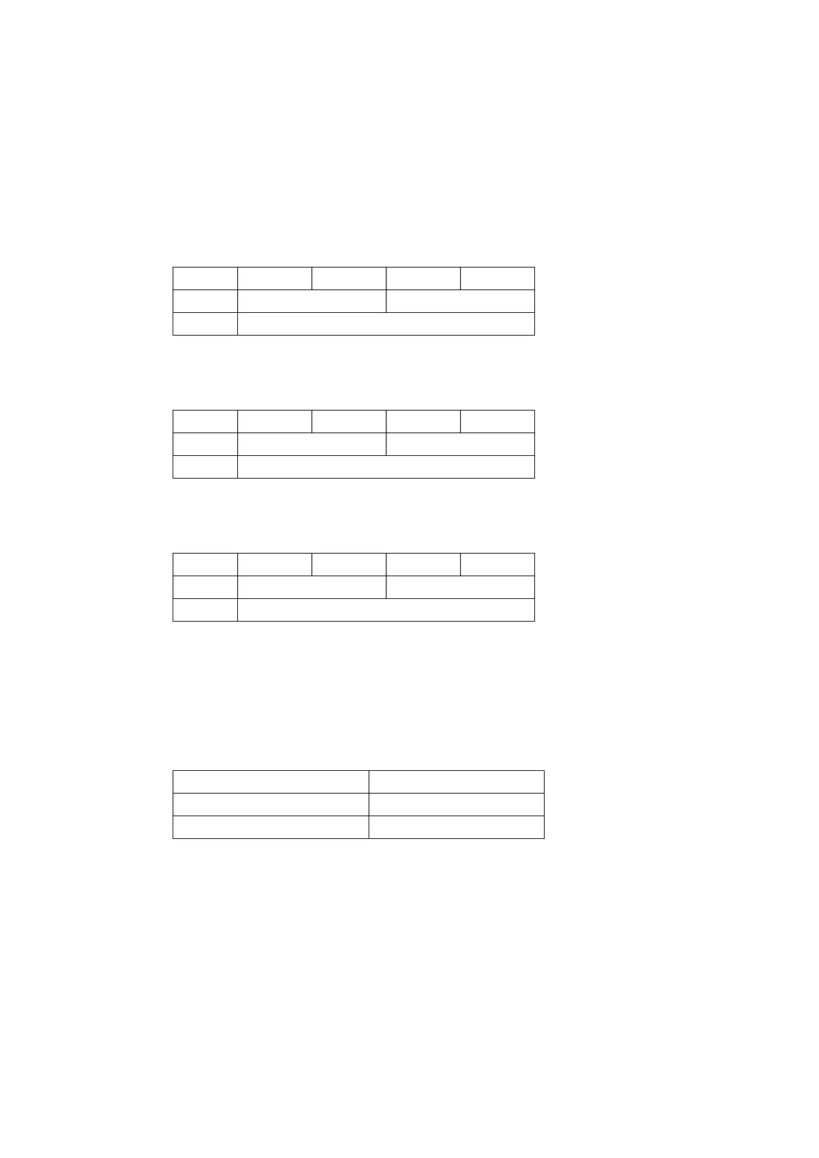
Allocation of each format is shown in the table below.
Table A4-5. Assignment of 8/16/32 bit value
8bit 0x12 0x34 0x56 0x78
16bit 0x1234(MSW) 0x5678(LSW)
32bit 0x12345678
Table A4-6. Assignment of 8/16 bits and F32
8bit 0x41 0x45 0x85 0x1E
16bit 0x4145(MSW) 0x851E(LSW)
F32 12.345
Table A4-7. Assignment of 8/16bit and Str
8bit 0x41 0x42 0x43 0x44
16bit 0x4142(MSW) 0x4344(LSW)
Str 'ABCD'
・ The 32-bit register is in the order of high word (MSW) followed by low word (LSW).
The following table shows the cases where 0x12345678 is assigned to address n of Modbus register.
Table A4-8. Relationship between 32-bit values and Modbus registers
32-bit value 0x12345678
Modbus register (address n) 0x1234(MSW)
Modbus register (n+1) 0x5678(LSW)
A4-6. Outline of 1 Holding/Input register map
・ The register map of the Switch starts from address 0.
・ The contents of registers No. 0 to 49 are switched according to the register type setting (No.103).
・ Registers No. 0 to 99 are read-only.
・ Registers after No.100 can be read and written.