24
Installation
Connections
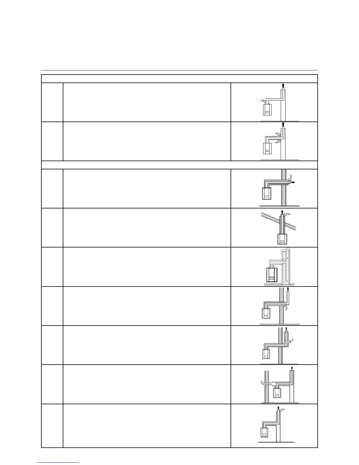
Air- / ue gas ducts - installation variants
Ambient combustion air, ø80 PP
B23 Flue gas duct into the chimney, aspiration of air from the surroundings.
End section of the waste gas duct above the roof.
B33 Flue gas duct into the chimney, aspiration of air from the surroundings.
End section of the waste gas duct above the roof.
Combustion air taken from the surroundings, ø 80/125 PP/sheet steel white
C13
C13x
Flue gas duct and suction air over the outer wall, in the same pressure
range.
C33
C33x
The waste gas and suction air ducts via the chimney must operate in the
same pressure range. Vertical end section of the waste gas duct.
C43
C43x
Suction air and waste gas duct via the chimney system, which is
integrated in the building.
C53
C53x
Section the air and waste gas exhaust to the outside, in areas with
dierentpressures.
Vertical end section of the waste gas duct.
C63*
C63x
Speciallydevelopedequipment,forconnectiontocertiedair-/wastegas
systems that operate separately from one another.
* Not permitted in Belgium
C83
C83x
Air suction on the outside of the building, waste gas duct via the chimney.
C93
C93x
Air and waste gas piping to the waste gas chimney, via installation in the
roof and in a humidity-resistant waste gas chimney.
Min. annular gap for waste gas piping:
Ø80 = 45mm
Ø100 = 50mm
Ø110 = 40mm