OPTIONAL ACCESSORIES
16-6 SM OU12HP 2-E.2 GB
16.5 Room Thermostat
Room Thermostat kit PN: 442298
Thermistor with connector PN: 442296
Before starting the connection verify that the unit is disconnected
from main power supply!!
ROOM THERMOSTAT INSTALLATION INSTRUCTIONS
Check the installation manual for further information
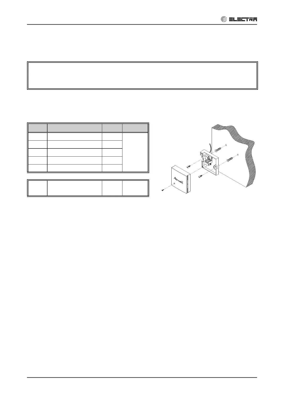
Supplied components list:
No. Item QTY PN
1 Thermostat box 1
442298
2 Shielded cable 1
3 Screws and plugs 2
4 LABEL 1
5 BAG 1
1
Extension cable with
connector
1
442296
Choosing location of installation:
xAway from air drafts
xAway from direct sun light rays
xAverage height – 1.5 meters above floor
xAway from any heat source
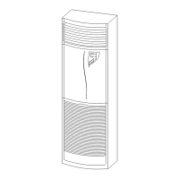
1. Install the thermostat box on the wall according the above location preferences. See figure 1.
2. Connect the shielded cable supplied to the thermostat box into points 3 and 9 (non polarity).
3. Disconnect the existing “RM” sensor from the indoor unit main controller.
4. Connect the other end of “RM” extension cable to the the sheilded cable. Also connect the
grounding fork terminal into the grounding terminal point.
5. In the indoor unit main controller, move the dip switch #2 to OFF position.
Figure 1